Search filter
Filter
Reset- Product data sheet (906)
- Installation drawing (888)
- Installation instructions (358)
- Tender texts (296)
- 3D model (181)
- Product scale drawing (147)
- Certificate (113)
- Declarations of performance (91)
- Cable plan (76)
- Declaration of conformity (73)
- Wiring diagram (43)
- Product declaration (LEED, DGNB, EPD) (43)
- User manual (35)
- Supplementary sheet (25)
- Flyer/folder (24)
- Product brochure (22)
- Type examination certificate (11)
- T&C / Data Protection (7)
- Software (5)
- Supplier information (4)
- Customer information (3)
- Safety analysis (2)
- Evaluation/comment (2)
3355 results found

Standard cable plan Powerturn F/R 1-leaf
DWG | 258 KB
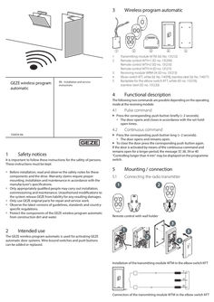
GEZE wireless programme automatic
3 Wireless program automatic … Connecting the receiving module … B … 1 … GEZE wireless program automatic EN Installation and service instructions … 3 … Transmitting module WTM (Id. No. 131212) Remote control WTH-1 (ID no. 131209) Remote control WTH-2 (ID no. 131210) Remote control WTH-4 (ID no. 131211) Receiving module WRM-24 (ID no. 131213) Elbow switch KFT, white (Id. No. 114078), stainless steel (Id. No. 114077) Backplate for the elbow switch KFT, white (ID no. 131219), stainless steel (ID no. 131220) … 4 … 4 … 1-channel connection of the receiving module WRM-24, e.g. to a door Optional cabling, if already existing push buttons available … B Pulse command Press the corresponding push button briefly (< … seconds). àà The door opens and closes in accordance with the set holdopen times. … 132674-05 … Safety notices It is important to follow these instructions for the safety of persons. These instructions must be kept. àà Before installation, read and observe the safety notes for these components and the drive. Warranty claims require proper mounting, installation and maintenance in accordance with the manufacturer's specifications. àà Only appropriately qualified people may carry out installation, commissioning and maintenance. Unauthorised modifications to the system release GEZE from liability for any resulting damages. àà Only use GEZE original parts for repair and service work. àà Observe the latest versions of guidelines, standards and countryspecific regulations. àà Protect the components of the GEZE wireless program automatic from construction dirt and water. Continuous command Press the corresponding push button long (> … seconds). àà The door opens and remains open. XX To close the door press the corresponding push button again. If the door is activated by means of the continuous command and remains open for a longer period, the message 37, 38, 39 or 40 “Controlling longer than … min” may be displayed on the programme switch. XX … Mounting / connection … Connecting the radio transmitter … In2 In1 A Out2 Out1 … 2 … Intended use 24V DCU-connector … DCU-connector … 1 … 21/23 … 2 21/23 GND 2-channel connection of the receiving module WRM-24, e.g. to two doors (same electric circuit) or two entrances at one door … Receiving module operating mode The operating mode is set by means of the DIP switch on the receiving module that has to be set correctly before initial commissioning. DIP switch DIP switch on the receiving module WRM-24 Pulsed operation (see chapter … ): … ON … 2 DIP1 = OFF DIP2 = OFF Pulsed and continuous operation (see chapter … ): ON Remote control with wall holder … 3 … Optional cabling, if already existing push buttons available * Factory setting … 5 … The GEZE wireless program automatic is used for activating GEZE automatic door systems. Wire-bound switches and push buttons can be added or replaced. … DIP1 = ON DIP2 = OFF Teach button Teach button at the receiving module WRM-24 Press the teach button on the receiving module for approx. … second in order to activate teach-in. àà The receiving module beeps 1× briefly every … seconds. àà The memory for the first channel is selected. XX Press the corresponding push button on the radio transmitter briefly within 30 seconds. àà The receiving module beeps 1× long as confirmation. àà The radio transmitter has been taught successfully and terminates teaching mode automatically. If further radio transmitters are to be taught, repeat the steps. XX The following two commands are possible depending on the operating mode at the receiving module: XX Teach-in of radio transmitters at a 1-channel connection 24V GND Functional description … DCU-connector … 1 … 21/23 Optional cabling, if already existing push buttons available … 2 Commissioning For safety reasons the radio transmitter can only be taught during the first … minutes after the operating voltage has been switched on at the drive. In2 In1 A Out2 Out1 … 6 … Teach-in of radio transmitters at a 2-channel connection Steps from chapter … must be carried out in order to teach-in the radio transmitter at the first channel. Teach-in at the second channel is done as follows: XX Press the teach button on the receiving module for approx. … second. àà The receiving module beeps 1× briefly every … seconds. XX Press the teach button again for approx. … second. àà The receiving module beeps 2× briefly every … seconds. àà The memory for the second channel is selected. XX Press the corresponding push button on the radio transmitter briefly within 30 seconds. àà The receiving module beeps 1× long as confirmation. àà The receiving module has been taught successfully and terminates teaching mode automatically. If further radio transmitters are to be taught, repeat the steps from chapter … and / or chapter … . A maximum of 85 radio transmitters can be taught per receiving module. If more than 85 radio transmitters are to be taught, additional receiving modules are to be connected. … Deleting radio transmitters For safety reasons the radio transmitter can only be deleted during the first … minutes after the operating voltage has been switched on. XX Press the teach button at the receiving module for approx. 10 seconds. àà The receiving module beeps 1× long as confirmation. àà All the taught radio transmitters have been deleted successfully from the memory. Taught radio transmitters can only be overwritten. If a taught radio transmitter is to be deleted, all the taught radio transmitters have to be deleted. … Installation of the transmitting module WTM in the elbow switch KFT YE GN BN KFT Connection of the transmitting module WTM in the elbow switch KFT >> … Maintenance / battery change … Remote control The battery service life is designed for approx. 30 000 operations. When the battery power declines, the LED begins to flash during operation. The battery should then be replaced by a new battery A23/MN21/P23GA (ID no. 131217). … Transmitting module The battery service life is designed for approx. 50 000 operations. When the battery power declines, the LED begins to flash during operation. The battery should then be replaced by a new CR 2032 battery (ID no. 131218). … Technical data Frequency: Transmission power: Range: Security: Power supply: … MHz <10 mW ERP approx. 30 m Rolling code WTH: WTM: WRM-24: Relay contact: Dimensions (W × H × D): WRM-24: 12 V, Battery A23/MN21/P23GA, 50 mA … V, CR 2032 battery, 220 mA 24 V, … mA (current consumption in standby) … outputs 100 mA, 48 V 78 × 51 × 23 mm 44 × 30 × 11 mm 52 × 47 × 23 mm IP 54 IP 20 IP 20 WTH: WTM: WRM-24: IP rating: WTH: WTM: WRM-24 Storage temperature: –20 to +85 °C Service temperature: … to +50°C Humidity: max. 95%, non-condensing … Declaration of conformity GEZE GmbH hereby declares that the wireless system type GEZE wireless program automatic complies with the Directives 2014/53/EU and 2011/65/EU. The complete text of the EU Declaration of Conformity is available at the following internet address: www.geze.com For EU countries: In compliance with Directive 2012/19/EU concerning Waste Electrical and Electronic Equipment (WEEE). Germany GEZE GmbH Niederlassung Süd-West Tel. +49 (0) 7152 203 594 E-Mail: leonberg.de@geze.com GEZE GmbH Niederlassung Süd-Ost Tel. +49 (0) 7152 203 6440 E-Mail: muenchen.de@geze.com GEZE GmbH Niederlassung Ost Tel. +49 (0) 7152 203 6840 E-Mail: berlin.de@geze.com GEZE GmbH Niederlassung Mitte/Luxemburg Tel. +49 (0) 7152 203 6888 E-Mail: frankfurt.de@geze.com GEZE GmbH Niederlassung West Tel. +49 (0) 7152 203 6770 E-Mail: duesseldorf.de@geze.com GEZE GmbH Niederlassung Nord Tel. +49 (0) 7152 203 6600 E-Mail: hamburg.de@geze.com GEZE Service GmbH Tel. +49 (0) 1802 923392 E-Mail: service-info.de@geze.com Austria GEZE Austria E-Mail: austria.at@geze.com www.geze.at Baltic States – Lithuania / Latvia / Estonia E-Mail: baltic-states@geze.com Benelux GEZE Benelux B.V. E-Mail: benelux.nl@geze.com www.geze.be www.geze.nl Bulgaria GEZE Bulgaria - Trade E-Mail: office-bulgaria@geze.com www.geze.bg China GEZE Industries (Tianjin) Co., Ltd. E-Mail: chinasales@geze.com.cn www.geze.com.cn Romania GEZE Romania S.R.L. E-Mail: office-romania@geze.com www.geze.ro GEZE Industries (Tianjin) Co., Ltd. Branch Office Shanghai E-Mail: chinasales@geze.com.cn www.geze.com.cn Russia OOO GEZE RUS E-Mail: office-russia@geze.com www.geze.ru GEZE Industries (Tianjin) Co., Ltd. Branch Office Guangzhou E-Mail: chinasales@geze.com.cn www.geze.com.cn Scandinavia – Sweden GEZE Scandinavia AB E-Mail: sverige.se@geze.com www.geze.se GEZE Industries (Tianjin) Co., Ltd. Branch Office Beijing E-Mail: chinasales@geze.com.cn www.geze.com.cn Scandinavia – Norway GEZE Scandinavia AB avd. Norge E-Mail: norge.se@geze.com www.geze.no France GEZE France S.A.R.L. E-Mail: france.fr@geze.com www.geze.fr Scandinavia – Denmark GEZE Danmark E-Mail: danmark.se@geze.com www.geze.dk Hungary GEZE Hungary Kft. E-Mail: office-hungary@geze.com www.geze.hu Singapore GEZE (Asia Pacific) Pte, Ltd. E-Mail: gezesea@geze.com.sg www.geze.com Iberia GEZE Iberia S.R.L. E-Mail: info.es@geze.com www.geze.es South Africa GEZE South Africa (Pty) Ltd. E-Mail: info@gezesa.co.za www.geze.co.za India GEZE India Private Ltd. E-Mail: office-india@geze.com www.geze.in Switzerland GEZE Schweiz AG E-Mail: schweiz.ch@geze.com www.geze.ch Italy GEZE Italia S.r.l E-Mail: italia.it@geze.com www.geze.it Turkey GEZE Kapı ve Pencere Sistemleri E-Mail: office-turkey@geze.com www.geze.com GEZE Engineering Roma S.r.l E-Mail: italia.it@geze.com www.geze.it Ukraine LLC GEZE Ukraine E-Mail: office-ukraine@geze.com www.geze.ua Korea GEZE Korea Ltd. E-Mail: info.kr@geze.com www.geze.com Poland GEZE Polska Sp.z o.o. E-Mail: geze.pl@geze.com www.geze.pl GEZE GmbH Reinhold-Vöster-Straße 21–29 71229 Leonberg Germany United Arab Emirates/GCC GEZE Middle East E-Mail: gezeme@geze.com www.geze.ae United Kingdom GEZE UK Ltd. E-Mail: info.uk@geze.com www.geze.com Tel.: 0049 7152 203 … Fax: 0049 7152 203 310 www.geze.com
PDF | 389 KB
TSA 160NT-F-IS (push) right hand door
PDF | 468 KB
ECturn transom installation opposite hinge side link arm
DWG | 625 KB
TSA 160 NT TSA 160 NT F TSA 160 NT F- IS TSA 160 NT Invers TSA 160 NT Z TSA 160 NT Z -Invers
TSA 160 NT Valid for variants: TSA 160 NT F TSA 160NT F-IS TSA 160NT Invers TSA 160 NT Z TSA 160 NT Z-Invers 135239-03 EN Wiring diagram TSA 160 NT Contents Symbols and illustrations … Validity … Product liability … 2 … Notes … Important safety instructions … Installation information … Safety-conscious working … Inspection of installed system … Commissioning and service … Disposal of the door system … 2 Abbreviations … 3 Electrical data … 4 Control … 5 Safety sensor open and close … Safety sensor GC 338 … Safety sensor GC 342 … 12 Safety sensor GC 334 … 14 Safety sensor GC 335 … 16 … Mechanical contact … 18 … Key switch … 19 … Contact sensor inside … 19 … Radar movement detector GC 302 R … 19 Radar movement detector GC 304 R … 20 Push button (potential-free normally opened contact) … 20 … Contact sensor outside … 20 … Radar movement detector GC 302 R … 20 Radar movement detector GC 304 R … 21 Push button (potential-free normally opened contact) … 21 … Radio activation … 21 10 Push And Go … 22 11 Configurable inputs … 22 … MPS … 22 Opening 2-leaf and 1-leaf … 22 Emergency lock … 23 Additional contact sensors (P-KI, P-KA) … 23 Switch functions … 23 Control reset … 24 Double push button (1-leaf / 2-leaf door opening) … 24 Operating mode switchover Off … 25 STOP … 25 Closing position monitoring, closing position blanking SIS, Push And Go … 26 WC control … 27 TSA 160 NT 12 Electric strike … 28 … 24V DC electric strike supplied on drive side … 28 Customer-supplied 12 V AC electric strike … 29 Bar message … 29 13 Mode of operation … 30 … Internal programme switch … 30 Mechanical programme switch (MPS, external programme switch) … 30 Mechanical programme switch (MPS-D, external programme switch) … 31 Keypad programme switch (TPS) … 31 Display programme switch (DPS) with OFF … 32 Display programme switch (DPS) without OFF … 32 14 2-leaf drives … 33 … TSA 160 NT IS-TS: Active leaf automated, passive leaf with TS 160 … 33 Two automated door leaves … 33 15 Smoke switch control unit … 34 16 Motor, solenoid valve … 35 17 Limit switch … 35 … Open position … 35 Wall blanking SIO … 35 18 Mains connection … 36 … TSA 160 NT 1-leaf … 36 TSA 160 NT IS-TS: Active leaf automated, passive leaf with TS 160 … 36 Two automated door leaves TSA 160 NT … 37 19 TSA 160 NT Invers at RWA-control panel … 38 20 Control … 39 21 Commissioning and service … 40 … Pre-conditions … 40 Carrying out commissioning … 40 Finish commissioning … 42 Changing the parameters of a 2-leaf drive … 42 22 Mode of operation … 44 23 Service menu … 44 … Service terminal ST220 … 44 Operation of ST220 … 44 Service mode ST220 … 44 Connecting service terminal ST220 … 45 Service menu ST220 … 45 24 Display programme switch DPS and Service push buttons S1, S2 … 53 … Display programme switch (DPS) … 53 Service buttons S1 and S2 … 53 DPS service menu and service buttons S1/S2 with LEDs … 55 Value table for service LEDs and display programme switch … 58 25 Fault messages … 59 … Fault display … 59 Fault messages service LEDs, DPS, ST220 … 59 Fault messages keypad programme switch … 60 … TSA 160 NT Symbols and illustrations Warning notices Warning notices are used in these instructions to warn you of property damage and personal injury. XX Always read and observe these warning notices. XX Observe all the measures that are marked with the warning symbol and warning word. Warning symbol Warning word Meaning Danger for individuals. DANGER Non-compliance will result in death or serious injuries. WARNING Danger for individuals. Non-compliance can result in death or serious injuries. CAUTION Danger for individuals. Non-compliance may lead to minor injuries. Further symbols and means of representation Important information and technical notes are highlighted to explain correct operation. Symbol Meaning means “important information” ; Information on avoiding material damage, understanding a concept or optimising workflows means “additional Information” XX Symbol for an action: This means you have to do something. XX If there are several actions to be taken, keep to the given order. Conforms to DIN 18650 / EN 16005 Symbol in a table or in information concerning safety sensors. Does not conform to DIN 18650 / EN 16005 Symbol in a table or in information on sensors that do not correspond to DIN 18650 / EN 16005. Fire protection door Symbol for fire protection door Not permissible for fire protec- Symbol “Not permissible for fire protection door” tion door Validity Valid for units with Hardware: DCU500 Rev. D Software: DCU5 V3.1 Product liability In accordance with the manufacturer's liability for their products as defined in the German “Produkthaftungsgesetz” (Product Liability Act), the information contained in this brochure (product information and proper use, misuse, product performance, product maintenance, obligations to provide information and instructions) is to be noted and followed. Failure to comply releases the manufacturer from his statutory liability. … TSA 160 NT Notes … Notes … Important safety instructions To ensure personal safety, it is important to follow these safety instructions. XX Keep these instructions. àà Only specialists who are authorised by GEZE are permitted to carry out installation, commissioning and maintenance. àà If unauthorised changes made to the system, GEZE cannot be made liable in any way whatsoever for any resulting damages. àà GEZE does not accept any warranty for combinations with third-party products. In addition, only original GEZE parts may be used for repair and maintenance work. àà Connection to the mains voltage must be carried out by a qualified electrician. Perform the power connection and equipment earth conductor test in accordance with VDE 0100 Part 610. XX Use an on-site automatic cut-out as the line-side disconnecting device, the dimensioning of which is matched to the type, cross-section, type of routing and ambient conditions of the on-site feeder. The automatic cut-out must have at least … A and max. 16 A. àà Attach safety stickers to glass door leaves, mat. no. 081476. XX In accordance with Machinery Directive 2006/42/EC, a safety analysis is to be performed and the door system marked in compliance with CE Marking Directive 93/68/EEC before the door system is commissioned. àà Observe the latest versions of directives, standards and country-specific regulations, in particular: àà ASR A1.7 “Directives for doors and gates” àà EN 16005 “Power operated pedestrian doorsets – Safety in use – Requirements and test methods” àà DIN 18650, Part … and Part … “Automatic door systems” àà “Guidelines for hold-open systems” àà DIN VDE 100-600 “Installation of low-voltage systems - Part … Tests” àà DIN EN 60335-2-103 “Household and similar electrical appliances - Safety; Particular requirements for drives for gates, doors and windows” àà Accident Prevention Regulations, in particular BGV A1 (VBG1) “General Regulations” and BGV A3 (VBG4) “Electrical Installations and Resources” Swing door drive as a hold-open device in accordance with DIN 18263-4 àà The hold-open function of the swing door drive must be cancelled in the event of a fire alarm, fault or manual triggering, the lock latch release (electric strike according to fail-secure principle) must be disabled and all the signal transmitters for opening the door leaves must be switched ineffective. àà The swing door drives may only be used on single-leaf and double-leaf doors if the door frame or, as the case may be, the passive leaf of the double-leaf doors is equipped with an electric strike that releases the lock latch and/or unlocks a safety catch with a spring-loaded latch. … Installation information àà The drive is designed exclusively for use in dry rooms. XX Use only the cables specified on the cable plan provided. Cables must be shielded in compliance with the wiring diagram. XX Always use insulated wire-end ferrules for wire cores. XX Insulate wires that are not used. XX Secure loose, internal drive cables with cable ties. XX Observe the maximum permitted overall current drain required to supply the periphery. … Safety-conscious working XX XX XX XX àà àà àà àà àà àà Secure the workplace against unauthorised entry. Watch the swivelling range of long system parts. Secure the cover/drive/roller guide rail or link arm against falling. Before carrying out work on the electrical system, cut the voltage supply (mains and rechargeable battery) and check that no voltage is present. When an Uninterruptible Power Supply (UPS) is used, the system will still be under voltage even when disconnected from the mains. Risk of injury by moving parts (drawing in of hair, clothing, …) when a drive is opened. Danger of injury caused by unsecured crushing, impact, drawing-in or shearing spots. Danger of injury due to sharp edges in the drive. Risk of injury due to glass breakage. Danger of injury through link arm or lever arm snapping back. Danger of injury when working at a great height. … Abbreviations … Inspection of installed system XX XX XX … Measures for checking safety and prevention of crushing, impact, shearing or drawing-in spots. Check the function of the presence sensors and movement detectors. Check the protective earth connection to all metal parts that can be touched. Commissioning and service XX … TSA 160 NT The values of parameter setting are only saved when the Service menu is closed. Disposal of the door system àà The door system is made up of materials that should be sent for recycling. For this purpose, the individual components should be sorted corresponding to material type: àà Aluminium (profiles, cover, …) àà Iron (lever arm, link arm, screws, …) àà Plastic àà Electronic components (electric strike, motor, control, transformer, sensors, …) àà Cables àà The parts can be disposed of at the local recycling depot or by a scrap recycling company. … Abbreviations Wire colours BN brown BK black BU blue GN GY YE green grey yellow OG PK RD orange pink red TQ turquoise VT violet WH white Connections, terminals and plugs AU ASF BS BGS DO DPS ES GF GND KA KB KI LK LS MPS MPS-D MVT NA NTZ OFF … Automatic Activation, passive leaf Hinge side Opposite hinge side Hold open Display programme switch Limit switch and internal programme switch Active leaf Ground Contact sensor outside Mechanical contact Contact sensor inside Luster terminal Shop closing Mechanical programme switch Mechanical programme switch Solenoid valve Night mode Mains Off OL PEx PS RS485 SF RES RM RSZ SCR SO SIS SL STOP TOE TPS TST WAB 24V Limit switch, open position Programmable input (x = … or 2) Programme switch Communication signal to DPS, TPS and second drive Passive leaf Reset switch Bar message Smoke switch control unit Screen Safety sensor, open Safety sensor, close Limit switch, closing position Stop Electric strike Key programme switch Test signal for safety sensors Limit switch, wall blanking Supply voltage for external devices, max. … A TSA 160 NT … Electrical data Electrical data Mains voltage 230 V AC –15 %, +10 % Frequency 50 Hz Protection rating I Capacity rating 300 W Mains connection Fixed connection (installation cable) Primary fuse … A (1-leaf drive) T4A (2-leaf drive) Control voltage for external components 24 V DC ±10% Output current control voltage 24 V 1200 mA permanently, 1400 mA briefly (5 s, duty rating 30 %) Fuse protection 24 V short-circuit proof, switch-off at … A Temperature range –15…+50 °C IP rating IP20 … KI … 2 21 … KA PE1 PE2 … 2 23 OFF SIS TOE 11 … 2 10 RS485-ASF SIO PS … 8 … 13 … 2 10 … 2 31 32 33 RS485 KB … 20 … 1 … 42 41 43 … 51 52 Control TSA 160 NT Control TSA 160 NT … Safety sensor open and close Safety sensor open and close XX XX In the case of 2-leaf systems connect the safety sensors of the active leaf with the active leaf control and those of the passive leaf with the passive leaf control. Install the sensor for monitoring closing on the door leaf, opposite hinge side. The sensor for monitoring closing can also be used as a contact sensor outside or inside. XX Setting the parameters: àà DPS: Set f1 to … 2 (“SIS and KI”) or … 3 (“SIS and KA”). àà ST220: Set “Signals”, “Input signals”, “SI1 – terminal SIS”, “SI1 function” to “SIS and KA” or to “SIS and KI”. àà S1, S2: Set parameter … to 02 (“SIS and KI”) or 03 (“SIS and KA”). If the SIS is activated during closing, the door reverses and opens again. àà TSA 160 NT: àà If a closing position limit switch is connected, the SIS is blanked as soon as the closing position is reached (see chapter 11, “Configurable inputs”, “Closing position limit switch”). àà Without closing position limit switch the SIS is only blanked 10 s after the closing process starts. If the SIS is activated within this time, the door opens. àà TSA 160 NT Invers: àà The SIS is blanked directly after the closing position has been reached. XX Install the sensor for monitoring opening on the door leaf, hinge side. àà If the SIO is activated during opening, the door stops. àà At detection the sensor output is open (0 V applied to SIS or SIO input). àà 2-leaf doors: àà Both door leaves stop when one of the two SIO sensors is activated, if the function “SIO Stop SF GF” is set in the configuration for the safety sensor open (SIO). XX Check function and correct setting of the sensors during commissioning and service. To operate the display programme switch DPS see chapter … , “Display programme switch (DPS)”. To operate the service terminal ST220 see chapter … , “Operation of ST220”. … Safety sensor GC 338 Follow installation instructions GC 338. àà Accessories: àà Spot finder( mat. no. 112321) XX The connector plug of the GC 338 has … poles. Terminal … is not occupied. XX XX Set DIP switch … (TST/SBY) on the GC 338 interface module to ON (factory setting). Setting the testing parameter: àà DPS: Set Te to 01 (testing with 24 V). àà ST220: Set “Output signals”, “Testing SI” to “Testing with 24 V”. àà S1, S2: Set parameter 11 to 01 “Testing with 24 V”. … Safety sensor open and close … .1 TSA 160 NT Monitoring closing and opening XX XX Setting the parameter contact type: àà DPS: Set s1 and s3 to … 2 (“normally closed contact”) (factory setting). àà ST220: Set the “Input signals”, “SI1 – terminal SIS”, “SI1 contact type” to “normally closed contact” and “SI3 – terminal SIO”, “SI3 contact type” to “normally closed contact” (factory setting). àà S1, S2: Set parameter … and … to 02 “normally closed contact”. Setting the function parameter: àà DPS: Set f1 to the desired function and f3 to … 5 (SIO stop) or … 6 SIO stop SF GF). àà ST220: Set the “Input signals”, “SI1 – terminal SIS”, “SI1 function” to the desired function and “SI3 – terminal SIO”, “SI3 function” to “SIO stop” or “SIO stop SF GF”. àà S1, S1: Set parameter … to the desired function. Set parameter 10 to 05 “SIO Stop” or 06 “SIO stop GF”. E S … 2 or … 1 E SIO 13 SIO 100mA … GY 24V … BN SIO … BK GND … BU SIS … WH SIGNAL … 2 … 4 10 Opposite hinge side Hinge side Door transmission cable GC 338 interface module S GND … 24V 10 TST SIS 11 SIS … 4 … 1 GND … 24V 10 TST TSA 160 NT … .2 Safety sensor open and close Monitoring opening XX XX Setting the contact type parameter: àà DPS: Set s3 to … 2 (“normally closed contact”) (factory setting). àà ST220: Set the “Input signals”, “SI3 – terminal SIO”, “SI3 contact type” to “normally closed contact” (factory setting) àà S1, S2: Set parameter … to 02 “normally closed contact”. Setting the function parameter: àà DPS: Set f3 to … 5 (SIO stop) or to … 6 SIO stop SF GF). àà ST220: Set the “Input signals”, “SI3 – terminal SIO”, “SI3 function” to “SIO stop” or “SIO stop SF GF”. àà S1, S1: Set parameter 10 to 05 “SIO Stop” or 06 “SIO stop SF GF”. … 2 E SIO 13 SIO 100mA SIGNAL … 24V … SIO … GND … SIS … GY … GND … 24V 10 TST BN BK BU WH … 4 … 2 … 4 … .3 Opposite hinge side Hinge side Door transmission cable GC 338 interface module S Monitoring closing XX XX … 2 … 4 Setting the contact type parameter: àà DPS: Set s1 to … 2 (“normally closed contact”) (factory setting). àà ST220: Set the “Input signals”, “SI1 – terminal SIS”, “SI1 contact type” to “normally closed contact” (factory setting). àà S1, S1: Set parameter … to 02 “normally closed contact”. Setting the function parameter: àà DPS: Set f1 to the desired function. àà ST220: Set the “Input signals”, “SI1 – terminal SIS”, “SI1 function” to the desired function. àà S1, S1: Set parameter … to the desired function. Hinge side Opposite hinge side Door transmission cable GC 338 interface module … 2 E SIS 11 SIS 100mA SIGNAL … 24V … SIO … GND … SIS … GY … GND … 24V 10 TST BN BK BU WH … 4 S 11 Safety sensor open and close … TSA 160 NT Safety sensor GC 342 àà Safety sensor GC 342 àà Follow installation instructions GC 342 àà Accessories (optional): àà Remote control, mat. no. 100061 àà For further accessories see installation instructions GC 342 Sensor position XX Install safety sensors on the door leaf as specified in the GC 342 installation instructions. XX Setting the testing parameter. àà DPS: Set Te to … 2 (testing with GND). àà ST220: Set “Output signals”, “Testing SI” to “Testing with GND”. àà S1, S2: Set parameter 11 to 02 “Testing with GND”. … .1 Monitoring closing and opening … 60 mA -UB +UB GN YE GND … 24V 10 TST SIS 11 GY SIS PK Test SIO … WH SIO COM + … 1 … 3 BN SIO 13 BU RD SIS … GND … 24V 10 TST … GC 342 hinge side GC 342 opposite hinge side Door transmission cable Settings GC 342 àà See installation instructions GC 342. àà GEZE recommends using the optional remote control to change the sensor parameters. Settings DCU5 XX Setting the contact type parameter: àà DPS: Set s1 and s3 to … 2 (normally closed contact) (factory setting). àà ST220: Set the “Input signals”, “SI1 – terminal SIS”, “SI1 contact type” to “normally closed contact” and “SI3 – terminal SIO”, “SI3 contact type” to “normally closed contact” (factory setting). àà S1, S2: Set parameter … and … to 02 “normally closed contact”. XX Setting the function parameter: àà DPS: Set f1 to the desired function and f3 to … 5 (SIO stop) or … 6 (SIO stop SF GF). àà ST220: Set the “Input signals”, “SI1 – terminal SIS”, “SI1 function” to the desired function and “SI3 – terminal SIO”, “SI3 function” to “SIO stop” or “SIO stop SF GF”. àà S1, S2: Set parameter … to the desired function. Set parameter 10 to 05 “SIO Stop” or 06 (SIO stop SF GF). 12 TSA 160 NT … .2 Safety sensor open and close Monitoring opening SIO 60 mA -UB +UB 13 BN SIO … GN GND … YE 24V 10 TST WH SIO PK SIS GY Test COM + BU RD … 1 … 2 GC 342 hinge side Door transmission cable Settings DCU5 XX Setting the contact type parameter: àà DPS: Set s3 to … 2 (normally closed contact) (factory setting). àà ST220: Set the “Input signals”, “SI3 – terminal SIO”, “SI3 contact type” to “normally closed contact” (factory setting). àà S1, S2: Set parameter … to 02 “normally closed contact”. XX Setting the function parameter: àà DPS: Set f3 to … 5 (SIO stop) or … 6 (SIO stop SF GF). àà ST220: Set the “Input signals”, “SI3 – terminal SIO”, “SI3 function” to “SIO stop” or “SIO stop SF GF”. àà S1, S2: Set parameter 10 to 05 “SIO Stop” or 06 (SIO stop SF GF). … .3 Monitoring closing SIS 60 mA -UB +UB 11 BN SIS … GN GND … YE 24V 10 TST WH SIO PK SIS Test … 1 … GY COM + BU RD … GC 342 opposite hinge side Door transmission cable Settings DCU5 XX Setting the contact type parameter: àà DPS: Set s1 to … 2 (normally closed contact) (factory setting). àà ST220: Set the “Input signals”, “SI1 – terminal SIS”, “SI1 contact type” to “normally closed contact” (factory setting). àà S1, S2: Set parameter … to 02 “normally closed contact”. XX Setting the function parameter: àà DPS: Set f1 to the desired function. àà ST220: Set the “Input signals”, “SI1 – terminal SIS”, “SI1 function” to the desired function. àà S1, S2: Set parameter … to the desired function. 13 Safety sensor open and close … TSA 160 NT Safety sensor GC 334 àà GC 334 module, mat. no. 126410 XX Follow the installation instructions. XX Set testing: àà DPS: Set Te to … 2 (testing with GND). àà ST220: Set “Output signals”, “Testing SI” to “Testing with GND”. àà S1, S2: Set parameter 11 to 02 “Testing with GND”. àà Max. … modules in series … .1 Monitoring closing and opening Setting the contact type parameter: àà DPS: Set s1 to … 2 (“normally closed contact”) and s3 to … 2 (“normally closed contact”) (factory setting). àà ST220: Set the “Input signals”, “SI1 – terminal SIS”, “SI1 contact type” to “normally closed contact” and “SI3 – terminal SIO”, “SI3 contact type” to “normally closed contact” (factory setting). àà S1, S2: Set parameter … and … to 02 “NC”. XX Setting the function parameter: àà DPS: Set f1 to the desired function and f3 to … 5 (“SIO stop“) or … 6 (“SIO stop SF GF“). àà ST220: Set the “Input signals”, “SI1 – terminal SIS”, “SI1 function” to the desired function and “SI3 – terminal SIO”, “SI3 function” to “SIO stop” or “SIO stop GF SF”. àà S1, S2: Set parameter … to the desired function. Set parameter 10 to 05 “SIO Stop” or 06 (SIO stop SF GF). àà Configuration of the GC 334 modules on the àà Hinge side: DIP1 = ON àà Opposite hinge side: DIP1 = OFF XX 14 … 1 … 60mA … - BN + GN … YE WH PK VT - BU + RD … 1 … 3 … 5 GC 334 module Opposite hinge side Hinge side Door transmission cable GC 334 opposite hinge side SIO 13 SIO … GND … 24V 10 TST SIS 11 SIS … GND … 24V 10 TST TSA 160 NT … .2 Safety sensor open and close Monitoring opening Setting the contact type parameter: àà DPS: Set s3 to … 2 (“normally closed contact”) (factory setting). àà ST220: Set the “Input signals”, “SI3 – terminal SIO” and “SI3 contact type” to “normally closed contact” (factory setting). àà S1, S2: Set parameter … to 02 “normally closed contact”. XX Setting the function parameter: àà DPS: Set f3 to … 5 (SIO stop) or … 6 SIO stop SF GF“). àà ST220: Set the “Input signals”, “SI3 – terminal SIO” and “SI3 function” to “SIO stop” or “SIO stop SF GF”. àà S1, S2: Set parameter 10 to 05 “SIO Stop” or 06 “SIO stop SF GF”. àà GC 334 module configuration: DIP1 = ON XX … .3 … 60mA - BN + GN … YE WH SIO 13 SIO … GND … 24V 10 TST PK VT + BU RD … 1 … 3 GC 334 module Door transmission cable GC 334 hinge side Monitoring closing Setting the contact type parameter: àà DPS: Set s1 to … 2 (“normally closed contact”) (factory setting). àà ST220: Set the “Input signals”, “SI1 – terminal SIS” and “SI1 contact type” to “normally closed contact” (factory setting). àà S1, S2: Set parameter … to 02 “normally closed contact”. XX Setting the function parameter: àà DPS: Set f1 to the desired function. àà ST220: Set the “Input signals”, “SI1 – terminal SIS” and “SI1 function” to the desired function. àà S1, S2: Set parameter … to the desired function. àà GC 334 module configuration: DIP1 = OFF XX … 60mA - BN + GN … YE WH PK SIS 11 SIS … GND … 24V 10 TST VT + BU RD … 1 … 3 GC 334 module Door transmission cable GC 334 opposite hinge side 15 Safety sensor open and close … .4 TSA 160 NT GC 334 connection over interface GC 334 The GC 334 interface is used to connect a customer's existing cable transition. … 2 … 1 60mA + + … 1 … 3 … 5 … SIS 11 SIS SIO GND 24V TST … 5 … GC 334 module Opposite hinge side Hinge side GC 334 hinge side Interface GC 334 Door transmission cable Safety sensor GC 335 XX XX XX XX XX XX 16 … SIO 13 … 2 10 … 3 Follow the installation instructions. Use the reference body, mat no. 120190, to set the detection area. Always install the master module near the hinge, connection with drive control takes place at the master module. Connect max. … slave modules to one master module. Open the configuration bridge at the last slave module or at the master module (if no slave modules connected). Setting the “Testing” parameter. àà DPS: Set Te to 01 (testing with 24 V). àà ST220: Set “Output signals”, “Testing SI” to “Testing with 24V”. àà S1, S2: Set parameter 11 to 01 “Testing with 24 V”. TSA 160 NT … .1 Safety sensor open and close Monitoring closing and opening XX XX Setting the contact type parameter: àà DPS: Set s1 to … 2 (“normally closed contact”) and s3 to … 2 (“normally closed contact”) (factory setting). àà ST220: Set the “Input signals”, “SI1 – terminal SIS”, “SI1 contact type” to “normally closed contact” and “SI3 – terminal SIO”, “SI3 contact type” to “normally closed contact” (factory setting). àà S1, S2: Set parameter … and … to 02 “NC”. Setting the function parameter: àà DPS: Set f1 to the desired function and f3 to … 5 (“SIO stop“) or … 6 (“SIO stop SF GF“). àà ST220: Set the “Input signals”, “SI1 – terminal SIS”, “SI1 function” to the desired function and “SI3 – terminal SIO”, “SI3 function” to “SIO stop” or “SIO stop SF GF”. àà S1, S2: Set parameter … to the desired function. Set parameter 10 to 05 “SIO Stop” or 06 “SIO stop SF GF”. … 60mA - … 2 + … WH … GN … 6 Test BN GY PK YE … 3 … SIS … 2 11 SIS … GND … 2 24V … 10 TST - … +6 … 8 SIO … 13 SIO … GND Test 10 60mA … WH … BN … GY … GN … 6 Test PK + … 24V 10 TST … YE … 1 … 3 … 5 GC 335 slaves GC 335 master opposite hinge side GC 335 adapter Door transmission cable GC 335 master hinge side 17 Mechanical contact … .2 Monitoring opening XX XX … .3 Setting the contact type parameter: àà DPS: Set s3 to … 2 (“normally closed contact”) (factory setting). àà ST220: Set the “Input signals”, “SI3 – terminal SIO” and “SI3 contact type” to “normally closed contact” (factory setting). àà S1, S2: Set parameter … to 02 “normally closed contact”. Setting the function parameter: àà DPS: Set f3 to … 5 (SIO stop) or … 6 SIO stop SF GF“). àà ST220: Set the “Input signals”, “SI3 – terminal SIO”, “SI3 function” to “SIO stop” or “SIO stop SF GF”. àà S1, S2: Set parameter 10 to 05 “SIO Stop” or 06 (SIO stop SF GF). … 2 60mA -1 +2 … 4 Test SIO 13 SIO … GND … 24V 10 TST … 6 … 1 … 3 GC 335 slaves Door transmission cable GC 335 master hinge side Monitoring closing XX XX … TSA 160 NT Setting the contact type parameter: àà DPS: Set s1 to … 2 (“normally closed contact”) (factory setting). àà ST220: Set the “Input signals”, “SI1 – terminal SIS” and “SI1 contact type” to “normally closed contact” (factory setting). àà S1, S2: Set parameter … to 02 “normally closed contact”. Setting the function parameter: àà DPS: Set f1 to the desired function. àà ST220: Set the “Input signals”, “SI1 – terminal SIS” and “SI1 function” to the desired function. àà S1, S2: Set parameter … to the desired function. … 60mA … -1 +2 … 4 Test SIS 11 SIS … GND … 24V 10 TST … 6 … 1 … 3 GC 335 slaves Door transmission cable GC 335 master opposite hinge side Mechanical contact àà The input KB is active in the operating modes AU, LS and NA. àà In the case of 2-leaf systems the mechanical contact can be connected to the active leaf control or to the passive leaf control. àà On selection the active leaf opens and, if switched on, the passive leaf. àà Upon activation, the output of the mechanical contact is closed (24 V applied at the KB input). àà Setting the contact type parameter: àà DPS: Set cB to 01 for “normally opened contact” or to … 2 for “normally closed contact”. àà ST220: Set the “Signals”, “Input signals”, “KB”, “KB contact type” to “normally opened contact” or “normally closed contact”. àà S1, S2: Set parameter 12 to 01 for “normally opened contact” or 02 for “normally closed contact”. àà A general activation delay ( D l, “Opening delay”) can be set for the input. The connection of a closing position limit switch is necessary for this (see chapter “Closing position monitoring, closing position blanking SIS, Push And Go“). Setting: àà DPS: Set D l to the desired delay time (0 s ... 20 s). àà ST220: Use the buttons or to set the “Door parameters”, “Opening delay” to the desired activation delay (0 s … 20 s) and press . àà S1, S2: Set parameter 22 to the desired opening delay (0 s … 20 s). 18 TSA 160 NT … Contact sensor inside Key switch àà Setting the contact type parameter: àà DPS: Set cB to 01 (factory setting). àà ST220: Set the “Signals”, “Input signals”, “KB”, “KB contact type” to “normally opened contact” (factory setting). àà S1, S2: Set parameter 12 to 01 ”normally opened contact“. àà Key switch SCT, single-pole, flush-mounted, AS500 without euro profile half cylinder, mat. no. 117996 àà Accessories: àà Euro profile half cylinder, mat. no. 090176 àà Additional contact, mat. no. 024467 … KB … 24V 20 KB Contact sensor inside àà The KI input is active in the operating modes AU and LS. àà In the case of 2-leaf systems the contact sensor inside can be connected to the active leaf control or to the passive leaf control. àà On activation the active leaf opens and, if switched on, the passive leaf. àà The sensor for monitoring closing can also be used as a contact sensor inside. àà Setting the parameters: àà DPS: Set f1 to … 2 . àà ST220: Set the ”Signals“, “Input signals”, “SI1 – terminal SIS”, “SI1 function” to “SIS and KI”. àà S1, S2: Set parameter … to 02 “SIS and KI”. àà For input KI an activation delay ( a I , “KI delay”) can be set if a closing position switch is installed (see chapter “Closing position monitoring, closing position blanking SIS, Push And Go“). This time is added to the general activation delay time ( D l, “Opening delay”). Setting the parameters: àà DPS: Set a I to the desired delay time (0 s ... 10 s). àà ST220: Use the buttons or to set “Signals” “Input signals”, “KI”, “KI delay” to the desired delay time (0 s … 10 s) and press . àà S1, S2: Set parameter 14 to the desired activation delay (00 s … 10 s). … Radar movement detector GC 302 R àà Upon activation, the output of the GC 302 R is closed (24V applied to the KI input). àà Setting the contact type parameter: àà DPS: Set cl to 01 (factory setting). àà ST220: Set the “Signals”, “Input signals”, “KI” and “KI contact type” to “normally opened contact” (factory setting). àà S1, S2: Set parameter 13 to 01 “normally opened contact” (factory setting). àà GC 302 R black, mat. no. 124087 àà GC 302 R according to RAL, mat. no. 124088 (remote control does not work with detector cover mounted, LED not visible). àà The GC 302 R is a directionally sensitive radar movement detector. àà Follow the installation instructions. GC 302 R 50 mA +UB … -UB … 3 … 5 WH BK BN BU KI … GND … 24V 21 KI 19 Contact sensor outside … Radar movement detector GC 304 R àà The GC 304 R is a direction-sensitive radar movement detector. àà Upon activation, the output of the GC 304 R is closed (24V applied to the KI input). XX Follow the installation instructions. XX Setting the contact type parameter: àà DPS: Set cl to 01 (factory setting). àà ST220: Set “Signals”, “Input signals”, “KI” and “KI contact type” to “normally opened contact” (factory setting). àà S1, S2: Set parameter 13 to 01 “normally opened contact” (factory setting). … TSA 160 NT GC 304 R 80 mA - UB … + UB … 3 … BN … GN GND 24V 21 KI YE … Push button (potential-free normally opened contact) àà Setting the contact type parameter: àà DPS: Set cl to 01 (“normally opened contact”) (factory setting). àà ST220: Set “Signals”, “Input signals”, “Contact sensor inside” and “Contact sensor inside, contact type” to “normally opened contact” (factory setting). àà S1, S2: Set parameter 13 to 01 “normally opened contact” (factory setting). … KI … WH KI … 24V 21 KI Contact sensor outside àà The input contact sensor outside is only active in the AU operating mode. àà In the case of 2-leaf systems the contact sensor outside can be connected to the active leaf control or to the passive leaf control. àà On selection the active leaf opens and, if switched on, the passive leaf. àà For the input KA an activation delay (aa, “KA delay”) can be set. The connection of a closing position limit switch is necessary for this (see chapter “Closing position monitoring, closing position blanking SIS, Push And Go“). This time is added to the general activation delay time ( D l, “Opening delay”). Setting the parameters: àà DPS: Set aa to the desired delay time (0 s ... 10 s). àà ST220: Use the buttons or to set “Signals”, “Input signals”, “KA”, “KA delay” to the desired delay time (0 s … 10 s) and press . àà S1, S2: Set parameter 16 to the desired activation delay (00 s … 10 s). … Radar movement detector GC 302 R àà For information see GC 302 R (KI). àà Upon activation, the output of the GC 302 R is closed (24V applied to the KA input). àà Setting the contact type parameter: àà DPS: Set cO to 01 (factory setting). àà ST220: Set “Signals”, “Input signals”, “Contact sensor outside”, “Contact sensor outside, type of contact” to “normally opened contact” (factory setting). àà S1, S2: Set parameter 15 to 01 “normally opened contact” (factory setting). 20 GC 302 R 50 mA +UB … -UB … 3 … 5 WH BK BN BU KA … GND … 24V 23 KA TSA 160 NT … Radio activation Radar movement detector GC 304 R àà The GC 304 R is a direction-sensitive radar movement detector. àà Upon activation, the output of the GC 304 R is closed (24V applied to the KI input). XX Follow the installation instructions. XX Setting the contact type parameter: àà DPS: Set cO to 01 (factory setting). àà ST220: Set “Signals”, “Input signals”, “KA” and “KA contact type” to “normally opened contact” (factory setting). àà S1, S2: Set parameter 15 to 01 “normally opened contact” (factory setting). … GC 304 R 80 mA - UB … + UB … 3 … KA … WH BN GN YE … 24V 23 KA … Push button (potential-free normally opened contact) àà Setting the contact type parameter: àà DPS: Set cO to 01 (factory setting). àà ST220: Set “Signals”, “Input signals”, “Contact sensor outside” and “Contact sensor outside, contact type” to “normally opened contact” (factory setting). àà S1, S2: Set parameter 15 to 01 “normally opened contact” (factory setting). … GND KA … 24V 23 KA Radio activation àà Follow the assembly and operating instructions. àà Setting the contact type parameter: àà DPS: Set cl or cO to 01 (“normally opened contact”) (factory setting). àà ST220: Set the “Signals”, “Input signals”, “KI”, “KI contact type” or “KA”, “KA contact type” to “normally opened contact”. àà S1, S2: Set parameter 13 or 15 to 01 “normally opened contact”. WRM-24 24V … 24V … GND … OUT1 … GND KI … or GND KA … GND … 24V … 24V 21 KI 23 KA OUT2 A B àà The receiving module WRM-24 can be activated with the transmitter module WTM and the remote control WTH. àà Transmitting module WTM, mat. no. 131212, for clipping into a plastic elbow switch. àà Remote control 1-channel, WTH-1, mat. no. 131209. àà Remote control 2-channel, WTH-2, mat. no. 131210. àà Remote control 4-channel, WTH-4, mat. no. 131211. àà Plastic elbow switch, àà white, mat. no. 114078, àà stainless steel, mat. no. 114077. àà Accessories: àà Back panel for plastic elbow switch, àà white, mat. no. 131219, àà stainless steel, mat. no. 131220. YE WTM GN BN WRM-24 GND … 24V … OUT1 KI … oder GND KA … G … 24V … 24 21 KI 23 KA 21 Push And Go 10 TSA 160 NT Push And Go WARNING Danger of injury due to crushing and shearing! XX During an activated Push And Go function door handles can form crushing and shearing points. àà The Push And Go function allows activation of the drive without contact sensors being used. àà When the Push And Go function is set, the drive opens the door automatically as soon as the door leaf is moved manually out of the closing position. TSA 160 NT Invers: àà The closing position limit switch (blue cam, see chapter … , “Open position”) triggers the Push And Go function at the same time. Connection of an additional closing position limit switch is not necessary. TSA 160 NT: àà The Push And Go function is only possible with closing position limit switch (see chapter … , “Closing position monitoring, closing position blanking SIS, Push And Go”). àà Setting the parameters: àà DPS: Set pU to value … 0 for Off, 01 for On. àà ST220: Set “Movement parameters”, “Push and Go” to the desired function on/off. àà S1, S2: Set parameter 31 to value 00 for Off, 01 for On. For TSA 160 NT Invers set parameter 30 (®u) “Solenoid valve” to 00 “no” in addition. 11 Configurable inputs àà Various special functions are assigned to the configurable inputs PE1 and PE2 (see chapter 23, “Service menu”). The contact type required for the desired function is specified in the service menu DPS or service menu ST220 section. àà The configurable input PE1 is only suitable for connection of normally opened or normally closed contacts. àà The configurable input PE2 is suitable for connection of normally opened or normally closed contacts as well as for connection of the monitored analogue signals emergency locking and stop. àà Setting the parameters: àà DPS: Set e1 or e2 to the desired function. àà ST220: Set “PE1”, “PE1 function“ or ”PE2”, “PE2 function” to the desired function. àà S1, S2: Set parameter 17 or 18 to the desired function. … MPS See chapter … , “Mechanical programme switch (MPS, external programme switch)” An MPS can only be connected to PE2. … Opening 2-leaf and 1-leaf àà The configurable inputs of the active leaf control can be used to change between the operating modes 2-leaf opening or 1-leaf opening as required (depending on the parameter setting). This can, for example, be advisable if the type of opening is switched by a timer via the available programme switching inputs (AU, DO). àà It is only possible to change the type of opening when the internal programme switch of the passive leaf drive is set to the OFF position (“0”). àà If the analogue programme switch MPS is connected, the type of opening cannot be changed through the configurable inputs since the MPS specifies “2-leaf opening” or “1-leaf opening” as fixed. àà Setting the parameters: àà DPS: Set e1 or e2 to … 3 (“selector switch summer”) or … 4 (“selector switch winter”). àà ST220: Set the “PE1 function” or “PE2 function” to “selector switch summer” or “selector switch winter”. àà S1, S2: Set parameter 17 or 18 to value 03 for “selector switch summer” or value … for “selector switch winter”. PE1 … 24V 51 PE1 22 or PE2 52 PE2 TSA 160 NT Configurable inputs … Emergency lock WARNING Danger of injury due to crushing and shearing! The safety sensors and obstruction are not evaluated. The door closes with the set force. XX If the door closes unexpected, move out of the danger zone. The emergency lock is not permitted with lipped doors and on emergency exits. àà The configurable input PE2 can be used to connect an emergency lock switch. àà When the emergency lock switch is activated, the contact is closed and … V is applied to the input PE2. The door closes and locks. The contact sensors KI, KA and KB as well as the safety sensors are blanked. Mode of operation hold open is aborted. àà The function requires a 20 kOhm terminating resistor for proper function. àà The door remains closed as long as the emergency lock signal is applied to the input. àà Setting the parameters: àà DPS: Set e2 to 07 (“emergency lock 20kOhm normally opened contact”). àà ST220: Set “PE2 function” to “emergency lock 20kOhm NO”. àà S1, S2: Set parameter 18 to 07 (“emergency lock 20kOhm NO”). PE2 … 24V 20 kΩ … 52 PE2 oder PE3 … 24V 53 PE3 Additional contact sensors (P-KI, P-KA) àà The configurable inputs can be used to connect additional closer contacts as contact sensors inside or contact sensors outside. àà Setting the parameters: àà DPS: Set e1 or e2 to … 8 for inside contact sensor or to … 9 for contact sensor inside. àà ST220: Set “PE1 function” or “PE2 function” to “P-KI activation NO” or “P-KA activation NO”. àà S1, S2: Set parameter 17 or 18 to value 08 for contact sensor inside or to the value 09 for contact sensor outside. àà Information see contact sensor inside (KI) or contact sensor outside (KA) … Switch functions General points àà Upon activation, the output of the push button is closed (24 V applied to the PE1 or PE2 input). àà In the case of 2-leaf systems the push button can be connected to the active leaf control or to the passive leaf control. XX Set the hold-open time at the active leaf control. àà If the push button is connected to the passive leaf control, both door leaves open when the switch function is activated, even if the “1-leaf” mode of operation is set if the passive leaf drive is switched on (internal programme switch in position “I” or “II”). … .1 Switch function Setting the parameters: àà DPS: Set e1 or e2 to … 0 for: 1st switch contact = open door / 2nd switch contact = close door If no second switch contact takes place, the door remains open until the mode of operation is changed. In the case of a 2-leaf drive, 2-leaf opening takes place if the push button is connected to the passive leaf drive. àà ST220: Set “PE1”, “PE1 function or PE2 function” to “Push button NO” for: 1st switch contact = open door / 2nd switch contact = close door àà S1, S2: Set parameter 17 or 18 to value 10 (Push button NO) for: 1st switch contact = open door / 2nd switch contact = close door If there is no second switch contact, the door remains open until the mode of operation is changed. 23 Configurable inputs TSA 160 NT … .2 Switch function hold-open time (OHZ) In the case of 2-leaf drives, the settings on the active leaf control determine the hold-open time. Setting the parameters: àà DPS: Set e1 or e2 to 11 (switch function OHZ NO) for: 1st switch contact = open door / 2nd switch contact = close door If the SIO is triggered before the hold-open time or the 2nd switch contact is activated, the hold-open time runs out and is not cancelled by the 2nd switch contact. The door closes at the latest after the hold-open time has expired: àà Oh for 2-leaf drive and 2-leaf mode of operation, if the push button on the passive leaf drive is connected. àà O ® for 1-leaf drive or 2-leaf drive and “1-leaf” mode of operation if the push button is connected to the GF drive. àà ST220: Set “PE1” or “PE2 function” to “Switch function OHZ NO” for: 1st switch contact = open door / 2nd switch contact = close door The door closes at the latest after the hold-open time has expired. àà S1, S2: Set parameter 17 or 18 to value 11 for: 1st switch contact = open door / 2nd switch contact = close door The door closes at the latest after the hold-open time has expired. … Control reset àà The control can be reinitialised via the configurable inputs. After the push button has been activated, the drive behaves like after the mains voltage has been switched on. àà Set the parameters with: àà DPS: Set e1 or e2 to … 3 (reset switch). àà ST220: Set “PE1 function” or “PE2 function” to “Reset switch NO”. PE1 GF or … 24V PE2 GF 51 PE1 … 52 PE2 Double push button (1-leaf / 2-leaf door opening) àà In the case of 2-leaf drives the door can open via the configurable inputs of the active leaf control in 1-leaf or 2-leaf mode as desired by pressing a button if the “1-leaf opening” operating mode setting is active. If the push button is pressed once, only the active leaf opens and closes after the 1-leaf hold-open time has expired. With two successive push button activations within … s open active leaf and passive leaf and close after the hold-open time 2-leaf has expired. àà Set the parameters with: àà DPS: Set e1 or e2 to … 4 (double push button). àà ST220: Set “PE1 function” or “PE2 function” to “Double push button”. PE1 GF … 24V 51 PE1 24 or PE2 GF 52 PE2 TSA 160 NT Configurable inputs … Operating mode switchover Off àà The configurable inputs can be used to change between the operating mode Off as required (depending on the parameter setting). This can, for example, be advisable if the mode of operation is switched by a timer via the available programme switching inputs (AU, DO). àà The operating mode change is not possible if the analogue programme switch MPS is connected since this specifies the operating modes Off in a fixed form. àà Setting the parameters: àà DPS: Set e1 or e2 to … 2 (Off , normally opened contact NO) or … 6 (OFF, normally closed contact NC). àà ST220: Set “PE1 function” or “PE2 function” to “Off normally opened contact NO” or “OFF normally closed contact NC”. àà S1, S2: Set parameter 17 or 18 to value 02 (Off normally opened contact NO) or 26 (OFF normally closed contact NC). PE1 … 24V 51 PE1 … or PE2 52 PE2 STOP The configurable inputs PE1 and PE2 can be used for connection of a stop push button or sensor strip. Input PE2 is also suitable for analogue evaluation. àà On activation, the door leaf stops (in case of 2-leaf systems both leaves) and remains at a standstill as long as the input is active. àà In the case of 2-leaf systems the stop push button can be connected to the active leaf control or to the passive leaf control. For PE1, PE2: àà Set the parameter contact type with: àà DPS: Set e1 or e2 to … 5 (Stop normally opened contact) or … 6 (Stop normally closed contact). àà ST220: Set “Signals”, “Input signals”, “PE1 function”, “PE2 function” to “Stop normally opened contact NO” or “Stop normally closed contact NC”. àà S1, S2: Set parameter 17 or 18 to the value 15 (Stop normally opened contact) or 16 (Stop normally closed contact). or E1 = 16 E1 = 15 E2 = 16 E2 = 15 For PE2: àà In order to ensure protection of persons as specified in DIN 18650 / EN 16005, a terminating resistor … kΩ or … kΩ must be connected to monitor the input. The terminating resistor must be connected directly to the switch contact. àà Set the parameter “Contact type” with: e2 to … 2 (Stop 1.2k) or 20 (Stop 2.0k) àà DPS: àà ST220: Set “Signals”, “Input signals”, “PE2”, “PE2 function” to “Stop … kOhm” or “Stop … kOhm”. àà S1, S2: Set parameter 18 to 12 (Stop … kOhm) or 20 (Stop … kOhm). Value 12, terminating with … kΩ Value 20, terminating with … kΩ 25 Configurable inputs TSA 160 NT … Closing position monitoring, closing position blanking SIS, Push And Go A closing position limit switch has to be used for closing position monitoring, for blanking the safety sensor close (SIS), for the Push And Go function as well as for the opening delay function. The closing position limit switch can be a supplementary cam switch that is mounted in the drive or a Reed switch that is mounted at the door. àà For notes and settings for the Push And Go function see chapter 10, “Push And Go”. àà When the door leaf is closed, the contact is closed, 24 V is applied to the input. àà Additional cam-operated switch, mat. no. 71154 or … Additional cam-operated switch closing position Set the parameters (closing position monitoring or closing position blanking SIS) àà For 1-leaf drive: àà DPS: Set e1 or e2 to … 6 (closing position GF NO). àà ST220: Set “Signals”, “Input signals”, “PE1” or “PE2” to “Closing position GF NO”. àà S1, S2: Set parameter 17 or 18 to value 06 (closing position GF NO). àà For 2-leaf drive àà Connect GF closing position limit switch to PE1 or PE2 of the active leaf control. àà Connect SF closing position limit switch to PE1 or PE2 of the passive leaf control. Parameter setting at GF control and SF control àà DPS: Set e1 or e2 to … 6 (closing position GF NO). àà ST220: Set “Signals”, “Input signals”, “PE1” or “PE2” to “Closing position GF NO”. àà S1, S2: Set parameter 17 or 18 to value 06 (closing position GF NO). 26 TSA 160 NT Configurable inputs … WC control Only use the fail-safe electric strikes. àà In the event of a power failure the door is freely passable. àà The “OCCUPIED” changeover switch switches between the AUTOMATIC and NIGHT modes of operation. àà When the switch is set to “OCCUPIED”, the NIGHT mode of operation is set and activation via KI or KA is not possible. The “OCCUPIED” signal lamps are switched on. àà The door can only be opened from the outside using the mechanical contact KB. àà Operation without display programme switch or keypad programme switch. Put the internal programme switch for the drive out of operation: XX Remove the tab connector of the red wire (24V) from the internal programme switch and insulate it. Parameter settings: XX Set e1 or e2 to 17 (PS-Night). Accessories: àà AS500 switch unit with illuminated display for disabled WC, mat. no. 47953 àà SLE, signal lamp, flush-mounted, AS500, AW, pre-mounted, mat. no. 115942 … DCU5 PS … 24V … AUT … DO DCU5 PE1 51 PE1 or DCU5 PE2 52 PE2 DCU5 … GND … 1 … AS500 switch unit “OCCUPIED” INSIDE SLE signal lamp “OCCUPIED” OUTSIDE 27 Electric strike 12 TSA 160 NT Electric strike Connect the electric strike of the active leaf to the active leaf control and the electric strike of the passive leaf to the passive leaf control. àà Floating relay contact, switching voltage/current max. 24 V AC/DC, … A. àà Activation of the electric strike is limited to … s plus the activation delay time by parameters D l. XX In case of an TSA 160 NT Invers use only emergency exit electric strikes, holding magnet or GEZE motor lock GEZE IQ Lock EL. àà Set the parameter electric strike type with: àà DPS: Set TO to the desired electric strike type (see Service menu DPS). àà ST220: Set the “Door parameters”, “Electric strike type” to the required type (see chapter … , “DPS service menu and service buttons S1/S2 with LEDs”). àà S1, S2: Set parameter 20 to the desired electric strike type. àà Holding magnet MA 500 with counter plate, mat. no. 024740, for the magnetic locking of emergency exit doors. àà Motor lock with panic function GEZE IQ Lock EL for 1-leaf doors. The GEZE IQ Lock EL is a self-locking anti-panic motor lock with external control. See wiring diagram for motor lock IQ Lock EL. IQ Lock SecuLogic set (Motor lock PZ-bored, complete, incl. flat face plate and strike plate, motor lock control, power supply cable for control, reed switch contact as well as open drip loop) XX Designation IQ Lock EL 9235 IQ Lock EL 9240 IQ Lock EL 9245 IQ Lock EL 7255 IQ Lock EL 7265 IQ Lock EL 7280 IQ Lock EL 7210 Distance 92 92 92 72 72 72 72 Backset 35 40 45 55 65 80 100 Mat. no. 103601 115013 103699 103700 103701 106571 106572 àà When a motor lock without feedback is used, a closing position limit switch is necessary (see chapter … , “Closing position monitoring, closing position blanking SIS, Push And Go”). An activation delay must be set using parameter dL (“Opening delay) which gives the motor lock time to unlock. àà Set the parameter D l (“Opening delay”) with: àà DPS: Set D l to the necessary time (00 ... 20 s). àà ST220: Set the “Door parameters”, “Opening delay” to the required time. àà S1, S2: Set parameter 22 to the required time (00 … 20). … 24V DC electric strike supplied on drive side GEZE electric strikes for standard applications, doors with access control GEZE electric strike type Mat. no. Current consumption Voltage Functions A5000--B 144590 200 mA (at 12 V) Continuous operation: 12 or 24 V DC ±15 % Fail-secure electric strike, 100 mA (at 24 V) Momentary operation: 12–48 V AC/DC standard applications, doors with access control A5000-FB 144632 200 mA (at 12 V) Continuous operation: 12 or 24 V DC ±15 % Fail-secure electric strike, with lock latch guide 100 mA (at 24 V) Momentary operation: 12–48 V AC/DC standard applications, doors with access control A5300--B 144631 200 mA (at 12 V) Continuous operation: 12 or 24 V DC ±15 % Fail-safe electric strike, 100 mA (at 24 V) standard applications A5000--E 145182 200 mA (with 8–11 V) Continuous operation: 8–28 V DC Fail-secure electric strike, 50 mA (with 12–24 V) Momentary operation: 8-28 V AC/DC standard applications, opening under sideload with direct voltage A5001--B 145183 200 mA (at 12 V) Continuous operation: 12 or 24 V DC ±15 % Fail-secure electric strike, with switch contact 100 mA (at 24 V) Momentary operation: 12–48 V AC/DC standard applications, doors with access control 28 TSA 160 NT Electric strike GEZE electric strike for fire protection doors GEZE electric strike type Mat. no. Current consumption FT500--B 144634 200 mA (at 12 V) 100 mA (at 24 V) FT501--E 144647 200 mA (with 8–11 V) with switch contact 50 mA (with 12-24 V) Voltage Continuous operation: 12 or 24 V DC ±15 % Momentary operation: 12–48 V AC/DC Continuous operation: 8–28 V DC Momentary operation: 8-28 V AC/DC àà Max. current consumption of 1000 mA, but pay attention to the total current consumption of all the components, especially for fail-safe electric strikes. àà Fail-secure electric strikes for TSA 160 NT: àà IQ eStrike A5000--E, mat. no. 145182 àà Fail-safe electric strikes for TSA 160 NT: àà IQ eStrike A5300--B, mat. no. 144631 XX Mount a free-wheeling diode 1N4007 (1), mat. no. 115293 (no free swing diode is required for GEZE electric strike). Functions Fail-secure electric strike, fire protection doors Fail-secure electric strike, fire protection doors, opening under sideload with direct voltage … 1 … 2 TOE … GND … 24V 31 TOEA 32 TOEB 33 RM Free swing diode Wire jumper … Customer-supplied 12 V AC electric strike Contact load output TOE with 12 V AC: max. … A ~ 12V AC ~ max. 1A TOE … GND … 24V 31 TOEA 32 TOEB 33 RM … Bar message àà Input RM blocks the activation of the drive when the door is locked. If the Input RM becomes active while the door is open, the door reverses and remains open. àà If a further electric strike is connected with àà Normally opened contact: Circuit the contacts in parallel. àà Normally closed contact: Switch the contacts in series. àà Setting the parameters: àà DPS: Set ®® to 01 (normally opened contact) or … 2 (normally closed contact). àà ST220: Set the “Signals”, “Input signals”, “Bolt contact type”, “Bolt contact type” to “ normally opened contact contact ” or “normally closed contact”. àà S1, S2: Set parameter 21 to value 01 (normally opened contact) or 02 (normally closed contact). TOE TOE … GND … GND … 24V … 24V 31 TOEA 31 TOEA 32 TOEB 32 TOEB 33 RM 33 RM Normally opened contact Normally closed contact 29 Mode of operation 13 TSA 160 NT Mode of operation àà To operate the display programme switch DPS see chapter … , “Display programme switch (DPS)”. àà To operate the service terminal ST220 see chapter … , “Operation of ST220”. … Internal programme switch àà Internal programme switch, 300 mm, mat. no. 105186 àà Internal programme switch, 640 mm, mat. no. 105187 Active leaf control àà The internal programme switch has the switch positions: àà NA (0) àà AU (II) àà DO (I). àà The mode is set with the AU and DO inputs. The drive switches to AU or DO mode if 24 V is applied to the corresponding input. In NA mode there is no signal at these inputs. GF ES I BU … II RD YE … WAB … OL … DO … 24V … 24V … 24V … AU Set the parameters (internal or external binary programme switch): àà DPS: Set ps automatic contact type to value 01 for “normally opened contact”. àà ST220: Set “Signals”, “Input signals”, “AU” to value “normally opened contact”. Set “Signals”, “Input signals”, “DO” to value “normally opened contact”. àà S1, S2: Set parameter 19 to value 01 for “normally opened contact”. àà The change of the operating mode with TPS or DPS is only possible if the internal programme switch has been set to the position NA (0). XX Passive leaf control àà The inputs AU (II) and DO (I) are used to switch the drive of the passive leaf on and off. The passive leaf runs synchronously with the active leaf (in compliance with the closing sequence), if 24 V is applied at one of the two inputs. SF ES I BU … II RD YE … WAB … OL … EIN … 24V … 24V … 24V … EIN … Mechanical programme switch (MPS, external programme switch) àà MPS, AS500, mat. no.113226 àà MPS-ST, with key, AS500, mat. no. 113227 àà Operating modes: OFF, NA, LS, AU 1-leaf, DO, AU 2-leaf XX Follow the installation instructions. àà At 2-leaf systems connect to the active leaf. àà The malfunction indication (LED) is not operable. àà Accessories: àà Surface-mounted cap, single, AS500, mat. no. 120503 XX Set the parameters (for MPS): àà DPS: Set ps , automatic contact type to value … 3 for “Analogue MPS”. àà ST220: Set “Signals”, “Input signals”, “AU” to value “Analogue MPS”. àà S1, S2: Set parameter 19 to value 03 for “Analogue MPS”. XX Disconnect internal programme switch (disconnect red wire and insulate). 30 TSA 160 NT Mode of operation … Mechanical programme switch (MPS-D, external programme switch) àà àà àà àà XX XX XX MPS-D, AS500, mat. no. 118417 MPS-D-ST, with key, AS500, mat. no. 118418 Operating modes: NA, AU, DO Accessories: àà Surface-mounted cap, single, AS500, mat. no. 120503 Set the parameters (internal or external binary programme switch): àà DPS: Set ps automatic contact type to value 01 for “normally opened contact” (factory setting). àà ST220: Set “Signals”, “Input signals” ,”AU” to value “normally opened contact” (factory setting). Set “Signals”, “Input signals” ,”DO” to value “normally opened contact” (factory setting). àà S1, S2: Set parameter 19 to value 01 for “normally opened contact” (factory setting). Disconnect internal programme switch (disconnect red wire and insulate). At 2-leaf systems connect to the active leaf. … Keypad programme switch (TPS) àà TPS, AS500, flush-mounted, mat. no. 113231 àà TPS SCT, AS500, flush-mounted, with key switch, without euro profile half cylinder, mat. no. 113232 àà Operating modes: OFF, NA, LS, AU, DO, Summer/Winter XX Follow the installation instructions. àà Accessories: àà Euro profile half cylinder, mat. no. 090176 àà Additional contact, mat. no. 024467 àà Surface-mounted cap, single, AS500, mat. no. 120503 àà Surface-mounted cap, double, AS500, mat. no. 128609 … LEDs for operating mode display. When a fault occurs, the LEDs àà Operation of the TPS is only possible, display a fault code (see chapter … , “Fault messages keypad àà if no active signal is applied to Terminals programme switch”). … (AU) and … (DO), … Display 1-leaf/2-leaf operation àà if terminals 1–44 are jumpered or the (LED lights up at 1-leaf operation, key push switch is triggered, LED flashes when maintenance is due) àà by unlocking by password if a password has been configured in the Service menu. àà Switching over between 1-leaf and 2-leaf operation: XX Press the push buttons simultaneously. 31 Mode of operation TSA 160 NT … Display programme switch (DPS) with OFF àà AS500, DPS with OFF, UP, alpine white, mat. no. 151524 àà Operating modes: OFF, NA, LS, AU, DO, 1-leaf/2-leaf opening XX Follow the installation instructions. àà If the PE2 function is set to “MPS”, only the mode of operation set using the MPS is displayed on the DPS. A change in the mode of operation is not possible with the DPS. àà The change in the mode of operation with the DPS is only possible if 24 V are not applied to terminal … (AU), terminal … (DO) nor PE1 or PE2 if PE1 or PE2 is configured to OFF, 2-leaf opening or 1-leaf opening. àà A change in the mode of operation is only possible when the key switch is activated or by unlocking with a password, if a password has been configured in the service menu. … RS485 … 1 OFF 100 mA … GND … 2 24V … 42 RS485-A 44 41 RS485-B 41 43 SCR 42 KB … 24V 20 KB … 2 Display 1-leaf/2-leaf operation (LED lights up for 1-leaf operation) Hidden service push button àà Switching over between 1-leaf and 2-leaf operation: XX Press the push buttons simultaneously. àà Keypad programme switch and display programme switch can be connected to the control at the same time. àà Operation at the TPS or DPS is not possible during the self-test, e.g. after changing the operating mode. The control can be configured using the display programme switch. Accessing the service menu XX Press the hidden service push button and simultaneously. Accessories: àà AS500, DPS with OFF and SCT, without euro profile half cylinder, flush-mounted, alpine white, mat. no. 155810 àà Key switch SCT, single-pole, flush-mounted, AS500 without euro profile half cylinder, mat. no. 117996 àà Euro profile half cylinder, mat. no. 090176 àà Surface-mounted cap, single, AS500, mat. no. 120503 àà Surface-mounted cap, double, AS500, mat. no. 128609 … Display programme switch (DPS) without OFF àà AS500, DPS without OFF, UP, alpine white, mat. no. 155809 àà Operating modes: NA, LS, AU, DO, 1-leaf/2-leaf opening XX Follow the installation instructions. àà Connection and other information, see … , “Display programme switch (DPS) with OFF”. 32 TSA 160 NT 14 2-leaf drives 2-leaf drives … TSA 160 NT IS-TS: Active leaf automated, passive leaf with TS 160 àà Programme switch, mat. no. 72526 XX Setting the parameters: àà DPS: Set ef to … 0 for 1-leaf drive Os (hold-open time KB) in such a way that the passive leaf only closes when the active leaf is in closing position. àà ST220: Set “Door parameters”, “Number of leaves” to “1-leaf drive”. Set “Movement parameters”, “Hold-open times”, “Mechanical contact” in such a way that the active leaf does not close until the passive leaf is in the closing position. àà S1, S2: Set parameter … to 00 for 1-leaf drive, parameter … (hold-open time KB) in such a way that the active leaf does not close until the passive leaf is in the closing position. àà Diode 1N4007, mat. no. 115293 Terminal strip intermediate cover Terminal strip SF Free swing diode Solenoid valve 24 V/160 mA GN GN 1N4007 … 2 … 4 RD BK … Two automated door leaves XX Setting the parameters: àà DPS: Set ef to 01 for active leaf drive or to … 2 for passive leaf drive. àà ST220: Set “Door parameters”, “Number of leaves” to “2-leaf active” or “2-leaf passive”. àà S1, S2: Parameter … to 01 for active leaf drive or to 02 for passive leaf drive. … .1 Connection via system cable RS485 àà RS485 connection cable, mat. no. 120048 RS485/ASF GF RS485_B … RS485_A … GND … RS485/ASF SF GN BN WH … RS485_B … RS485_A … GND … .2 Connection via standard cable RS485 Do not connect terminal 2. RS485 GF GND … RS485 SF … GND 24V … 2 24V RS485-A 42 42 RS485-A RS485-B 41 41 RS485-B SCR 43 43 SCR 33 Smoke switch control unit 15 TSA 160 NT Smoke switch control unit àà For 2-leaf drives the mains cut-off printed circuit board from the TSA 160-F accessories is installed in the passive leaf drive. XX Please note the installation and operating instructions of the smoke switch control unit. XX Setting the parameters: àà DPS: Set parameter a T to value … 3 . àà ST220: Set “Door parameters”, “Drive type” to the corresponding value. àà S1, S2: Set parameter 29 to value 03. àà In the event of a fire alarm, the mains voltage supply to the drive is interrupted by the mains cut-off printed circuit board. àà TSA 160 NT F closes through spring force. With 2-leaf doors, both leaves close. àà The smoke switch control unit is connected to the mains cut-off printed circuit board. àà The power disconnection circuit board places a load of approx. 35 mA on the smoke switch control unit. XX A manual trigger switch marked “Close door” must be installed directly at the door. àà Circuit breaker, AS500, mat. no. 116266 XX The reset switch from the TSA 160-F accessories is connected to the mains cut-off printed circuit board. XX Following a fire alarm or restoration of power supply. the reset switch must be pressed to put the equipment back into operation. XX Check the reset function during commissioning and servicing. 10 … HOD … GND T4AH … 2 … 4 Mains fuse, on site *) Main switch, on site**) Door drive (1-leaf or 2-leaf) TSA 160 NT F (with VDS approval for fire protection doors) TSA 160 NT ZR (without VDS approval) Fuse terminal strip, fuse 5×20 mm, T4AH/250 V AC … 6 … 8 … 10 Ferrite sleeve Earthing base plate Earthing drive hood Mains cut-off printed circuit board External holding open GC 151, GC 161 *) The customer must use an on-site automatic cut-out as the line-side disconnecting device, the dimensioning of which is matched to the type, cross-section, type of routing and ambient conditions of the on-site feeder (at least … A, maximum 16 A). **) Necessary in accordance with EN 60335-1, section … . 34 … TSA 160 NT 16 Motor, solenoid valve Motor, solenoid valve àà TSA 160 NT EN3-6 àà Hydraulic unit, mat. no. 019603 àà Motor capacitor, mat. no. 058821 àà 1~ motor, 220-230 V, … A, 50 Hz cos phi … , … kW, S2-6 Min., WSK 140 °C, C … µF, 400 V DB, IP44, EN60034 … 2 Solenoid valve Solenoid valve 24 V/160 mA 17 Limit switch … Open position TSA 160 NT XX Set the blue cam so that the limit switch is operated in the open position of the door. TSA 160 NT Invers XX Set the blue cam so that the limit switch is operated in the closing position of the door. To take the strain off the lock latch, a motor runon time HL (0 s … s) can be set, during which the motor presses the door leaf further into the closing position. … 2 Yellow cam: Wall blanking SIO Blue cam: TSA 160 NT Open position TSA 160 NT Invers closing position Setting the parameters: àà DPS: Set hl to the required motor run-on time. àà ST220: Set “Movement parameters”, “Motor run-on time” to the required run-on time. àà S1, S2: Set parameter 23 (HL) to the required motor run-on time. … Wall blanking SIO If the door moves towards a wall when opened, set the yellow cam so that the SIO is blanked (skipped) before the wall is detected. àà The yellow cam can be used for monitoring the closing position if the wall blanking function is not required. XX 35 Mains connection 18 TSA 160 NT Mains connection … TSA 160 NT 1-leaf àà Drive nominal power 300 W … 2 … 4 … 6 … Mains fuse (on site) *) Main switch (provided by customer) **) Door drive unit Fuse terminal strip, fuse 5×20 mm, T4AH/250 V AC Earthing base plate Earthing drive hood Ferrite sleeve T4AH … *) The customer must use an on-site automatic cut-out as the line-side disconnecting device, the dimensioning of which is matched to the type, cross-section, type of routing and ambient conditions of the on-site feeder (at least … A, maximum 16 A). **) Necessary in accordance with EN 60335-1, section … . … TSA 160 NT IS-TS: Active leaf automated, passive leaf with TS 160 àà Drive nominal power 300 W àà Cable harness intermediate cover kit , L = 2120, mat. no. 130132 àà 230 V fuse terminal strip, mat. no. 120522 10 T4AH … 2 … 4 … Mains fuse, provided by customer *) Main switch, on site**) Door closer, passive leaf Fuse terminal strip, fuse 5×20 mm, T4AH/250 V AC Ferrite sleeve … 7 … 9 10 Mains plug door closer passive leaf Base plate Drive hood Intermediate hood kit Active leaf drive *) The customer must use an on-site automatic cut-out as the line-side disconnecting device, the dimensioning of which is matched to the type, cross-section, type of routing and ambient conditions of the on-site feeder (at least … A, maximum 16 A). **) Necessary in accordance with EN 60335-1, section … . 36 TSA 160 NT Mains connection … Two automated door leaves TSA 160 NT àà Drive nominal power … x 300 W … T4AH … 2 … 4 Mains fuse (on site) *) Main switch (provided by customer) **) passive leaf drive Fuse terminal strip, fuse 5×20 mm, T4AH/250 V AC … 6 … 8 … Ferrite sleeve Earthing base plate Earthing drive hood Intermediate cover kit Active leaf drive *) The customer must use an on-site automatic cut-out as the line-side disconnecting device, the dimensioning of which is matched to the type, cross-section, type of routing and ambient conditions of the on-site feeder (at least … A, maximum 16 A). **) Necessary in accordance with EN 60335-1, section … . 37 TSA 160 NT Invers at RWA-control panel 19 TSA 160 NT TSA 160 NT Invers at RWA-control panel àà Accessory ZR-Invers, mat. no. 090769 àà With 2-leaf drives the power disconnection circuit board from the accessory ZR-Invers is mounted in the passive leaf drive. XX Follow the mounting and operating instructions of the SHEV control panel. XX Setting the parameters: àà DPS: Set parameter a T to value … 5 … 6 . àà ST220: Set “Door parameters”, “Drive type” to value “TSA 160 NT Invers” or “TSA 160 NT Z-Invers”. àà S1, S2: Set parameter 28 to value 05 or 06. XX Set drive type to 05 or 06 for TSA 160 NT Invers. àà When the smoke-heat extractor is activated by the SHEV control panel the mains voltage supply to the drive is interrupted by the mains cut-off printed circuit board. àà TSA 160 NT Invers opens by means of spring force. With 2-leaf doors, both leaves open. XX The 24 V alarm output of an RWA control panel is connected to the power disconnection circuit board. àà The power disconnection circuit board places a load of approx. 35 mA on the RWA control panel. RWA ALARM … 24V … 230V 50Hz L GND … 4 … BK … 2 BK L T4AH BN N BU … 4 BU N BU PE GN/YE PE … 2 … GN/YE + … - … 1 … 2 BN BU … 1 … 3 … Mains fuse, provided by customer *) Main switch, on site**) Door drive TSA 160 NT Invers (1-leaf or 2-leaf) Fuse terminal strip, fuse 5×20 mm, T4AH/250 V AC DCU5 NTZ1 … 1 … 5 … 7 … 9 Ferrite sleeve Earthing base plate Earthing drive hood Mains cut-off printed circuit board Jumper connector from the accessory ZR-Invers *) The customer must use an on-site automatic cut-out as the line-side disconnecting device, the dimensioning of which is matched to the type, cross-section, type of routing and ambient conditions of the on site feeder (at least … A, maximum 16 A). **) Necessary in accordance with EN 60335-1, section … . 38 TSA 160 NT Control àà àà àà àà DCU5 control, mat. no. 118444 Terminal bag, mat. no. 124448 S1, S2: Button for configuring/setting parameters LED1 through LED5: LEDs to display the operation mode, faults, parameters and parameter values RS485 SIS SIO KA KI S1 LED … (OG) LED … (OG) … LED … (OG) LED … (OG) RS485 / ASF LED … (RD) S2 + PROG KB PS TOE PE1 PE2 … 2 NTZ2 MVT ES … NTZ1 20 Control MOT DCU5 control unit DCU5 power unit 39 Commissioning and service 21 TSA 160 NT Commissioning and service Commissioning and service can be carried out with the display programme switch DPS, the service terminal ST220 or using the push buttons S1 and S2. àà Parameter setting using the buttons S1 and S2 of the control see chapter … , “Service buttons S1 and S2”. àà In case of parameter setting of the control using the push buttons S1 and S2, the RS485 connection between the active leaf and passive leaf control can remain. àà In case of parameter setting using the ST220 the active leaf and passive leaf configurations have to be carried out separately. Then the drives can be configured with an existing bus connection. àà In case of parameter setting of the control with DPS, the RS485 connection between the active leaf and passive leaf control has to be disconnected. … Pre-conditions àà àà àà àà àà Assembly is complete (see assembly and service instructions for the drive). Electrical installation is complete. Sensors are correctly configured and aligned. Internal programme switch at the active and passive leaf drive set to … (NIGHT/OFF). If available, external programme switch MPS or MPS-D set to NIGHT operating mode. … Carrying out commissioning … .1 Preparation For the ST220 push button functions, see chapter … , “Operation of ST220”. For DPS and S1, S2 push button functions, see 24, “Display programme switch DPS and Service push buttons S1, S2”. XX XX XX XX Switch off the mains power supply of the drive. Disconnect the RS485 connection to the active and passive leaf control (connector RS458/ASF or connector RS485). If necessary remove TPS and connect DPS to the active leaf control. Switch on the mains power supply of the drive. … .2 Commissioning with ST220 Configuring a brand-new 1-leaf drive In the menu “Door parameters”: àà In the submenu “Number of leaves”: “1-leaf drive”. àà In the menu “Type of installation”: “Electric strike type“ àà In the menu “Signals”, submenu “Input signals”: àà “SI1 – terminal SIS”, “SI1 contact type” àà “SI1 – terminal SIS”, “SI1 function” àà “SI3 – terminal SIO”, “SI3 contact type” àà “SI3 – terminal SIO”, “SI3 function” àà In the menu “Signals”, submenu “Output signals”: “Testing SI” XX Set further parameters if appropriate (see chapter … , “Service menu ST220”), in particular “Drive type”, “Type of installation” Type of bolt contact”. Configuring a brand-new 2-leaf drive XX Switch the mains supply voltage off. XX Set the internal programme switch at the active leaf drive to “II AUT” or, if available, the MPS-D to “Automatic”. XX Disconnect the RS485 connection active leaf control – passive leaf control. XX Connect the service terminal ST220 to the active leaf control. XX Switch on the 230 V mains supply voltage. XX With TSA 160 NT F press the reset switch. àà In the menu “Door parameters”, submenu “Number of leaves”: “2-leaf active” for active leaf control. XX Exit the service menu. “DCU500 GF” appears on the display. XX Set the internal programme switch on the passive leaf drive to “II AUT”. XX Connect the service terminal ST220 to the passive leaf control. àà In the menu “Door parameters”, submenu “Number of leaves”: “2-leaf passive” for passive leaf control. XX Exit the service menu. “DCU500 SF” appears on the display. 40 TSA 160 NT Commissioning and service Switch the mains supply voltage off. Re-establish the RS485 connection active leaf control – passive leaf control. XX Switch the mains supply voltage on again. XX With TSA 160NT F: Press the reset switch. Separate parameter setting for the controls is no longer necessary. The drive for which parameter setting is to take place (GF or SF) can be selected via the service terminal. XX Set further parameters, in particular: àà “Door parameters”: “Number of leaves”, “Drive type”, “Type of installation”, “Type of electric strike” àà “Input signals”: “SI1 contact type”, „SI1 function”, “SI3 contact type”, “SI3 function”, “Bolt contact type”, “AU contact type” àà “Output signals”: “Testing SI” XX XX If all contact of the door leaf with persons is to be avoided, safety sensors for monitoring opening and closing have to be mounted in accordance with DIN 18650 and be tested by the control. XX Check the running behaviour of the door and adjust other parameters if necessary. Clear the fault memory of the controls: XX Select the control via “Active leaf Para” or “Passive Leaf Para” respectively: XX Use “Diagnosis”, “Fault memory”, “Clear current faults”, “Yes” and “Clear old faults” – “Yes” to clear the fault memory of the selected control. XX Unplug ST220. The installation is complete (see installation instructions of the corresponding swing door drive). Sensors are correctly configured and aligned. XX Clear the detection area of the sensors. Electrical installation is complete. … .3 Commissioning with DPS Configuring a brand-new 2-leaf drive XX Switch the mains supply voltage off. XX Set the internal programme switch to “II AUT”. XX Disconnect the RS485 connection active leaf control – passive leaf control. XX Connect DPS with the active leaf control. XX Switch the mains voltage supply on. XX With TSA 160 NT F press the reset switch. XX Open the Service menu by pressing the hidden service push button and the ENTER push button (exit only) at the same time. XX Change parameter ef from “ … 0 ” (1-leaf drive) to 01 (2-leaf active). XX Set further parameters on the active leaf control, in particular: àà Set ef (Number of leaves), a T (Drive type), ht (Type of installation), TO (Type of electric strike), si (SI1 contact type), fi (SI1 function), s3 (SI3 contact type), f3 (SI3 function), ®® (Bolt contact type), ps (AU contact type), Te (Testing SI) XX Exit the service menu. XX Set the internal programme switch on the passive leaf drive to “II AUT”. XX Connect DPS with the passive leaf control and open the Service menu via DPS. XX Change parameter ef from … 0 (1-leaf drive) to … 2 (2-leaf passive) XX Set further parameters on the passive leaf control, in particular: àà Set ef (Number of leaves), a T (Drive type), ht (Type of installation), TO (Type of electric strike), si (SI1 contact type), fi (SI1 function), s3 (SI3 contact type), f3 (SI3 function), ®® (Bolt contact type), ps (AU contact type), Te (Testing SI) XX Exit the Service menu by pressing the hidden Service push button and the push button x (night mode) at the same time. XX Switch off the mains power supply of the drive. XX Disconnect DPS from the control again. XX Set up RS485 connection active leaf/passive leaf control again (connector RS485/ASF or connector RS485). XX Switch on the mains voltage. XX For TSA 160 NT F: Press the reset switch. If all contact of the door leaf with persons is to be avoided, safety sensors for monitoring opening and closing have to be mounted in accordance with DIN 18650 and be tested by the control. 41 Commissioning and service TSA 160 NT … .4 Commissioning via service push buttons S1 and S2. Configuring a brand-new drive For 2-leaf drives, the RS485 connection can be maintained between active leaf and passive leaf control. The parameters are set directly at the respective control via the Service push buttons. Active leaf drive: XX 1-leaf drive: Set parameter “01” (Number of leaves) to “00” (1-leaf drive) (factory setting). XX 2-leaf drive: Change parameter “01“ (Number of leaves) from “00” (1-leaf drive) to “01 “(2-leaf active). XX Set further parameters on the active leaf control, in particular: àà “29” (Drive type), “27” (Type of installation), “20” (Type of electric strike), “07” (SI1 contact type), “08” (SI1 function), “09” (SI3 contact type), “10” (SI3 function), “21” (Bolt contact type), “11” (Testing SI) Passive leaf drive: XX Change parameter “01“ (Number of leaves) from “00” (1-leaf drive) to “02 “(2-leaf passive). XX Set further parameters on the passive leaf control, in particular: àà “29” (Drive type), “27” (Type of installation), “20” (Type of electric strike), “07” (SI1 contact type), “08” (SI1 function), “09” (SI3 contact type), “10” (SI3 function), “21” (Bolt contact type), “11” (Testing SI) … Finish commissioning Switch off the mains power supply of the drive. Reverse the hold-open of the active leaf in the open position. XX Switch on the mains power supply of the drive. XX With TSA 160 NT F press the reset switch. XX Check function and detection areas of all contact sensors. XX Check the function and detection areas of the safety sensors for monitoring closing and opening. At sensor strips: XX Check each individual sensor module. XX Check the angle of the hiding of the safety sensor open and if necessary correct the setting of the limit switch wall blanking. XX If necessary correct the settings of the limit switch (open position/close position). XX XX … Changing the parameters of a 2-leaf drive Parameter S1, S2 … 7 … 9 10 11 20 21 19 29 27 42 DPS ef s1 f1 s3 f3 Te TO ®® ps aT hT ST220 Number of leaves Safety … contact type Safety … function Safety … contact type Safety … function Testing Electric strike type Bar message Automatic contact type Drive type Type of installation Description Active leaf/passive leaf Testing safety sensors Selection of the electric strike Contact for bar message Selection of function Au input Stop type TSA 160 NT Commissioning and service … .1 Configuring the active leaf control àà For parameter setting with the service terminal ST220, the control to be configured can be selected via the Service menu. àà For parameter setting with the service push buttons S1 and S2, parameter setting can take place directly at the control to be configured. àà For parameter setting with the DPS, selection of the control to be configured (active or passive leaf) is not possible. Parameter setting with the DPS is carried out as follows: XX If connected, set the internal programme switch II (AUT) or MPS to AUT. XX Switch off the mains power supply of the drive. XX With 2-leaf drive, disconnect the RS485 connection active leaf/passive leaf control (connector RS485/ASF or connector RS485). XX Connect DPS to the active leaf control. XX Switch on the supply voltage of the drive. XX With TSA 160 NT F press the reset switch. XX Open the Service menu by pressing the hidden service push button and the ENTER push button (exit only) at the same time. XX Carry out the required parameter settings. XX Exit the Service menu by pressing the hidden Service push button and the push button x (night mode) at the same time. XX Switch off the mains power supply of the drive. XX Disconnect DPS from the control again. XX With 2-leaf drive, re-establish the RS485 connection active leaf/passive leaf control (connector RS485/ASF or connector RS485). XX Switch on the mains voltage. For TSA 160 NT F: XX Press the reset switch. XX Check the changed functions and if necessary adjust. … .2 Configuring the passive leaf control àà For parameter setting with the service terminal ST220, the control to be configured can be selected via the Service menu. àà For parameter setting with the service push buttons S1 and S2, parameter setting can take place directly at the control to be configured. àà For parameter setting with the DPS, selection of the control to be configured (active or passive leaf) is not possible. Parameter setting with the DPS is carried out as follows: XX If connected, set the internal programme switch II (AUT) or MPS to AUT. XX Switch off the mains power supply of the drive. XX Disconnect the RS485 connection to the active leaf/passive leaf control (plug RS485/ASF or plug RS485). XX Connect the DPS to the passive leaf control. XX Switch on the supply voltage of the drive. XX With TSA 160 NT F press the reset switch. XX Open the Service menu by pressing the hidden service push button and the ENTER push button (exit only) at the same time. XX Carry out the required parameter settings. XX Exit the Service menu by pressing the hidden Service push button and the push button x (night mode) at the same time. XX Switch off the mains power supply of the drive. XX Disconnect DPS from the control again. XX Set up RS485 connection active leaf/passive leaf control again (connector RS485/ASF or connector RS485). XX Switch on the mains voltage. For TSA 160 NT F: XX Press the reset switch. XX Check the changed functions and if necessary adjust. 43 Mode of operation 22 TSA 160 NT Mode of operation LED … to LED … are used to display the set operating mode. … ○ ○ ○ ○ ○ ○ 23 … ○ ○ ○ ● ○ ● … ○ ○ ● ○ ○ ● … ○ ● ○ ○ ● ○ … ● ○ ○ ○ ● ○ Mode of operation OFF Night mode Exit only Automatic 1-leaf (AU Winter) Hold open Automatic 2-leaf (AU Summer) Service menu … Service terminal ST220 àà Service terminal ST200, mat. no. 087261 àà The drive can be commissioned with service terminal ST220, software version from v2.1. … Operation of ST220 Key Function Cursor upwards Increase number value Scroll upward (if key is pressed longer than … s) Cursor downwards Decrease number value Scroll downward (if key is pressed longer than … s) Cancel input Any input can be cancelled by pressing the x key. The input position then changes to the first menu position or one menu level back. Select Update display Accept new value Display directly after connection GEZE Service terminal … XXXXXYWWJJZZZZZZV Software version ST220 V2.1 Serial number ST220 … Service mode ST220 àà The system changes to Service mode when the service terminal is connected to the DCU5. àà Service is possible in modes of operation LS, AU and DO. àà In Service mode, the door remains in operation in the current operating mode. Display after connection establishment for door control TSA160 NT … DCU500 xy Automatic closed XX 44 D0 Drive type Software version … Hardware version E1 “xy”: “GF” for active leaf, “SF” for passive leaf Mode of operation Door mode Only exit the Service menu on the start screen, otherwise the parameter settings will not be saved. TSA 160 NT Service menu … Connecting service terminal ST220 … 2 21 RS485 KB SIO PS … 8 … SIS TOE KA KI … 2 23 PE1 PE2 11 … 2 10 … 2 31 32 33 … 13 … 2 10 … 51 52 … 2 42 41 43 … 20 The service terminal ST220 is connected to the control component of the DCU5 at connection RS484 (1). RS485-ASF … Service menu ST220 … .1 Parameter setting 2-leaf drives Carry out parameter setting for the active leaf/passive leaf individually without RS485 connection. àà DPS: Parameter “ef” to value … for “2-leaf active” or value … for “2-leaf passive” àà ST220: “Door parameters”, “Number of leaves” to “2-leaf active” or “2-leaf passive” àà S1, S2: Set parameter … to value 01 for “2-leaf active” or value 02 for “2-leaf passive” XX Establish an RS485 connection. XX Press the “↵” button. As the start for the configuration a selection window for parameter setting of the active leaf or passive leaf is displayed. XX Selection of active leaf/passive leaf parameter setting Selection of the parameter setting GF or SF Start GF or SF? Active leaf Para* Passive leaf Para Setting of active leaf parameter setting Setting of passive leaf parameter setting If the active leaf is selected, an “*” is displayed as the selection symbol. For the passive leaf a “+”. … .2 Main menu A 4-digit password must be entered before the main menu can be accessed: àà Password entry is only necessary if the menu is password-protected. Password 0--* XX Use XX Apply with and to select the PIN for the password consisting of digits and characters. . 45 Service menu TSA 160 NT … .3 Mode of operation Designation Mode of operation Opening type Setting values Off Night mode Exit only Automatic Hold open 2-leaf Open 1-leaf Open Explanation Operating mode setting Open active and passive leaves at activation Only active leaf opens Opening of the door via ST220 Open door (press button 1×) … .4 Door parameters Designation Number of leaves Drive type Type of installation Setting values 1-leaf drive 2-leaf active 2-leaf passive Unknown TSA 160 NT TSA 160 NT Z TSA 160 NT F TSA 160 NT Invers TSA 160 NT Z Invers Unknown KM BS GLS KM BG GST Explanation Active leaf drive passive leaf drive Z F KM Transom installation BS Hinge side BG Opposite hinge side GLS Guide rail GST Link arm Entry of the serial number: 000000000000 Drive ser. no. Pulling Fire protection Change value with confirm with cancel with Maintenance by operating time by cycles … 12 … 99 … 500,000 … 3,000,000 months Cycles Electric strike type No electric strike Fail-secure Fail-safe Motor lock Working close pressure Closed-circuit current close pressure Motor close pressure Solenoid valve No Yes 46 and , confirm with , . Only with TSA 160 NT Invers: The electric strike is relieved through close pressure of the door leaf before opening. 0...20 Opening delay , . Change value with cancel with and , s Period which the motor lock has to unlock before the drive opens the door. Only with TSA 160 NT Invers Door is kept in closing position by electric strike. Solenoid valve de-energised. Door is kept in closing position by solenoid valve. TSA 160 NT Service menu … .5 Movement parameters Designation Hold-open times Setting values 2-leaf (summer) 1-leaf (winter) Mechanical contact Close delay GF Dyn extension Explanation … .. … .. 10 .. 12 .. 20 .. 25 .. 50 60 … .. … .. 10 .. 12 .. 20 .. 25 .. 50 60 … .. … .. 10 .. 12 .. 20 .. 25 .. 50 60 … .. … .. 15 16 Yes No s s s s With activation via KB Time starts to expire as soon as the passive leaf starts to close. 16: Setting in accordance with DIN 18650/EN 16005. Time starts to expire as soon as the passive leaf has reached the closing position (closing position limit switch necessary). Automatic extension of the hold-open time at increased usage frequency … .. … .. 10 .. 12 .. 20 .. 25 .. 50 60 … sec. … .. … .. 10 .. 20 .. 50 × … s Can only be set for TSA 160 NT Invers. After the limit switch has been reached the motor is activated again for the duration of the run-on delay set. No Only with closing position limit switch. (limit switch not necessary Yes for TSA 160 NT Invers) Delay SF Motor follow-up time Push and Go … .6 Signals Input signals Designation SI1 - terminal SIS Setting values Current state SI1 contact type SI1 function SI3 - terminal SIO Current state SI3 contact type SI3 function Bolt contact type Current state Bolt contact type SI1 - terminal SIS1 Z-> inactive K->normally closed contact F -> SIS rev Not used Normally closed contact SIS rev SIS and KI SIS and KA SI3 - terminal SIO1 Z-> inactive K->normally closed contact F -> SIS rev Not used Normally closed contact SIO stop SIO SF GF Bolt contact type Z-> inactive K -> normally opened contact F-> lock contact Normally opened contact Normally closed contact Explanation Display Input SIS without function Reverse when closing Reverse when closing, KI in closing position Reverse when closing, KA in closing position Display Input SIO without function Stop when opening Use stop function from GF or SF Display 47 Service menu Designation KB TSA 160 NT Setting values Current state KB contact type KI Current state KI contact type KA KI delay Current state KA contact type AU KA delay Current state AU contact type DO Current state DO contact type PE1 Current state PE1 function 48 KB Z-> inactive K->normally closed contact Not used Normally opened contact Normally closed contact KI Z-> inactive K -> normally opened contact A -> … s Not used Normally opened contact Normally closed contact … .. 90 × … s KA Z-> inactive K -> normally opened contact A -> … s Not used Normally opened contact Normally closed contact … .. … .. 90 × … s AU Z-> inactive K -> normally opened contact Not used Normally opened contact Normally closed contact analogue MPS DO Z-> inactive K -> normally opened contact Not used Normally opened contact Normally closed contact PE1 Z-> inactive K -> not used F -> not used Not used OFF NO Switchover summer NO Switchover winter NO Sabotage NC Closing position GF NO Explanation Display Input KB without function Display Input KI without function Display Input KA without function Display Input AU without function Display Input DO without function Display Input PE1 without function Switchover to OFF (normally opened contact) For the connection of a push button for the summer function. Only for switching from 1-leaf to 2-leaf opening, not for actually opening the door. For the connection of a push button for the winter function. Only for switching from 2-leaf to 1-leaf opening, not for actually opening the door. Permanently switched. If the contact is interrupted KB is not evaluated in the night mode of operation. All other functions remain the same. Closing position contact of the door leaf àà For 1-leaf Door àà For 1-leaf Door drive with manual passive leaf (door closer): Closing position contact of the active leaf àà For 2-leaf door: Active leaf contact to GF control, passive leaf contact to SF control TSA 160 NT Designation Service menu Setting values P-KI activation P-KA activation Switch function NO NO NO Switch function hold- NO open time (OHZ) PE2 Current state PE2 function Reset switch NO Double push button NO Stop normally opened contact Stop normally closed contact PS-NA PS-LS Closed position SF WC control 1-leaf opening OFF normally closed contact PE2 Z-> inactive K -> not used F -> not used Not used OFF Switchover summer NO Switchover winter NO Sabotage NC Explanation Additional contact sensor KI Additional contact sensor KA With 2-leaf assemblies the push button can be connected to the active leaf control or to the passive leaf control. When the push button is pressed once, the drive opens the door. When the push button is pressed again, the drive closes the door. If the push button is connected to the passive leaf control opening and closing when both door leaves are activated if the internal programme switch of the passive leaf control is set to AUT. With 2-leaf assemblies the push button can be connected to the active leaf control or to the passive leaf control. When the push button is pressed once, the drive opens the door and closes after the hold-open time has expired. When the push button is pressed again (within the hold-open time) the drive closes the door without waiting for the hold-open time to expire. If the push button is connected to the active leaf, the 1-leaf hold-open time is used for 1-leaf use and the 2-leaf hold-open time for 2-leaf use. For restarting the drive. Function as reset. Press … x: GF opens; Press … x: SF also opens For connection of a stop push button NC NO NO NO NO NC Night mode programme Exit only programme SF or door closer closed. with IO 420 Only on the active leaf (2-leaf drive) Switchover to OFF Display NO NO Input PE2 without function Switchover to OFF (normally opened contact) For the connection of a push button for the summer function. Only for switching from 1-leaf to 2-leaf opening, not for actually opening the door For the connection of a push button for the winter function. Only for switching from 2-leaf to 2-leaf opening, not for actually opening the door. Permanently switched. If the contact is interrupted KB is not evaluated in the night mode of operation. All other functions remain the same. 49 Service menu Designation TSA 160 NT Setting values Closing position GF NO Emergency lock 20kOhm NO P-KI activation P-KA activation Switch function NO NO NO Switch function hold- NO open time (OHZ) Stop … kOhm 50 Reset switch NO Double push button NO Stop normally opened contact Stop normally closed contact PS-NA PS-LS Closed position SF Stop … kOhm NO WC control 1-leaf opening OFF normally closed contact NO NO NC Explanation Closing position contact of the door leaf àà For 1-leaf Door àà For 1-leaf Door drive with manual passive leaf (door closer): Closing position contact of the active leaf àà For 2-leaf door: Active leaf contact to GF control, passive leaf contact to SF control The input can be used to connect an emergency lock switch. When the emergency lock switch is activated, the contact is closed and … V is applied to the input. The door closes and locks. The contact sensors KI, KA and KB are blanked. The door remains closed as long as the emergency lock signal is applied to the input. Additional contact sensor (P-KI, P-KA). For connection of additional closing contacts. With 2-leaf assemblies the push button can be connected to the active leaf control or to the passive leaf control. When the push button is pressed once, the drive opens the door. When the push button is pressed again, the drive closes the door. If the push button is connected to the passive leaf control opening and closing when both door leaves are activated if the internal programme switch of the passive leaf control is set to AUT. With 2-leaf assemblies the push button can be connected to the active leaf control or to the passive leaf control. When the push button is pressed once, the drive opens the door and closes after the hold-open time has expired. When the push button is pressed again (within the hold-open time) the drive closes the door without waiting for the hold-open time to expire. If the push button is connected to the active leaf, the 1-leaf hold-open time is used for 1-leaf use and the 2-leaf hold-open time for 2-leaf use. For the connection of a stop push button with … kOhm terminating resistor. For restarting the drive. Function as reset. … × press = 1-leaf Open … × press = 2-leaf Open For connection of a stop push button. NC NO NO NO NO Night mode programme Exit only programme SF or door closer closed For the connection of a stop push button with … kOhm terminating resistor. Protection in accordance with EN 16005/DIN 18650. with IO 420 Only on the active leaf (2-leaf drive) Switchover to OFF (electric strike) TSA 160 NT Service menu Output signals Designation Testing SI Setting values Current state Testing SI Explanation Display Z-> inactive K -> not used F -> no testing No testing Testing with 24 V Testing with GND Testing switched off Diagnosis Designation Current values Setting values Inputs Outputs Internal values Statistics current conditions Inputs Outputs Fault memory Current fault SI1, SI3 RM KB, KI, KA AU DO Wall elimi Motor swit S1, S2 PE1 PE2 TOE Test MAG current position Voltages Cycles Hours Hours Ser SI1, SI3 RM KB, KI, KA AU DO Wall elimi Motor swit S1, S2 PE1 PE2 TOE Test MAG Fault … Fault … Fault … Fault … Old faults Fault … Fault … Fault … Fault … on off closed / open / open / close 24 V external Explanation … V / 24 V … V / 24 V … V / 24 V Voltage at the terminal in V … V / 24 V … V / 24 V … V / 24 V 0V/5V … V / 24 V Voltage at the terminal in V … V / 24 V … V / 24 V … V / 24 V Solenoid valve Voltage at the terminal in V Number of operating cycles since last maintenance Number of operating hours since last maintenance Hours until next maintenance The logical state of the signal is displayed (on/off) The current state is displayed (on/off) Solenoid valve Cause … Cause … Cause … Cause … Cause … Cause … Cause … Cause … Cause … Cause … Cause … Cause … Cause … Cause … Cause … Cause … 51 Service menu Designation TSA 160 NT Setting values Delete current faults No Yes No Yes Default setting No Yes Delete maintenance No Yes Password Change PW S1 Password old 0000 Password new ---Changing PW DPS TPS Password old 00 Password new -Clear old faults Language 52 deutsch english francais svensk Explanation Clear currently active faults Clear old faults Reset all the values to the factory settings Clear the maintenance values Password PW S1: for access to the service menu with ST220. Password PW TPS/DPS: is used to enable the TPS or DPS instead of enabling via a key switch. Disabling reoccurs automatically after … minute without push button activation. The first digit specifies how often the key has to be activated and the second digit how often the key has to be activated to release operation of the TPS / DPS. Entry of the password with ST200: XX Change digit with or . XX Confirm digit and change to next position with . àà Abort with x. àà Display of the current position by the asterisk under it. XX After completing entry, press to accept the password. After … minute without a button being pressed or when the service menu is accessed again, the password is required before changes to the operating mode setting or to the parameter settings can be carried out. The password has to be set separately for the active leaf and passive leaf drive. The active leaf drive and the passive leaf drive can have different passwords. Important information: àà When the password for ST220 is set, access to the service menu via DPS is no longer possible. àà If the password has been forgotten, a special flash file with which the password on the control can be reset to 00 has to be requested from GEZE. àà The password cannot be deleted by installing a new software version. TSA 160 NT 24 Display programme switch DPS and Service push buttons S1, S2 Display programme switch DPS and Service push buttons S1, S2 … Display programme switch (DPS) The DPS can be used for commissioning and servicing, mat. no. 151524: àà for changing the drive parameters àà for teaching the drive àà for diagnosis Mode of operation Na Night mode aU Exit only Automatic DO Hold open ls Service mode × Cancel and return to first menu level Confirm Scroll up increase value Scroll down Reduce value … 2 … OFF Change – – + simultaneously 2-leaf operation 1-leaf operation Service button (1) Change operating mode / service mode + simultaneously … Of OFF … 2 … 4 Service button Position unknown Illuminated for maintenance Lights up at 1-leaf operation Service button S1 Service-LEDs Service button S2 … 2 … … Service buttons S1 and S2 The service push buttons S1 and S2 as well as the service LEDs have the following functions: àà Opening and changing drive parameters àà Querying diagnosis data (states, values, faults) During normal operation the LEDs indicate the current mode of operation. The mode of operation can be changed using keys S1 and S2. Function Input and reaction Open/exit the parameter menu XX Simultaneously press buttons S1 and S2 longer than … s. LED5 flashes slowly, corresponding to the selected parameter level: Level 1: … pulse + … s pause Level 2: … pulses + … s pause LED1 through LED4 display the parameter. XX Briefly press button S2 (+) or button S1 (–). Select the parameter Switch to value setting Change value XX Hold down push button S1 longer than … sec. In the value menu, LED5 is off and LED1 through LED4 display the value in accordance with the value table. XX Briefly press button S2 (+) or button S1 (–). Confirm value XX Press button S1 longer than … s. Value setting without exiting value change XX Press button S2 longer than … s. Reset the values to the factory settings XX Set parameter 24 (factory settings) to 01 . 53 Display programme switch DPS and Service push buttons S1, S2 TSA 160 NT System messages àà If one or more faults are pending, these are displayed consecutively alternatively with the current mode of operation in encoded form with service LEDs … to 4. àà The red LED5 flashes quickly (10 Hz) on the fault display. àà The mode of operation is displayed for … s, the respective error message for … s. Service mode àà Individual parameters can be set for the control in service mode. àà Within the first … minutes of the mains voltage being switched on, the device can be changed to service mode using keys S1 and S2. àà There is a time limit to changing to service mode using keys S1 and S2 so that safety-related parameters are not changed unintentionally during operation. àà It is possible to change from any mode of operation to the service mode. àà The control automatically changes back to normal mode if no key is pressed in service mode for … minutes. àà In service mode, the control behaves in the same way as in the OFF mode of operation, the drive does not open and close automatically. àà The door can be opened and closed manually. Changing to the parameter selection menu XX Simultaneously press keys S1 and S2 longer than … s. The control changes to the parameter selection menu. In this menu, the red LED5 flashes once (parameter level 1) or twice (parameter level 2) at … Hz. The parameters are indicated in coded form by the other … LEDs. The required parameters are selected using keys S1 (–) and S2 (+). Changing to the value menu XX Press key S1 for longer than … s. The control changes to the value menu. àà All … LEDs are used for coding the values. àà The required value is selected using keys S1 (–) and S2 (+). àà After key S1 has been kept pressed for more than … s the control takes over the value indicated. àà Input can always be aborted by pressing key S2 for more than … s; the control then changes back to the value menu or the parameter menu. àà Service mode is quit by pressing keys S1 and S2 simultaneously for more than … s. Display values service LEDs 54 … ○ ○ ○ ○ ○ ○ ○ ○ ○ ○ ○ ○ ○ … ○ ○ ○ ○ ○ ○ ○ ○ ● ● ● ● ● … ○ ○ ○ ○ ● ● ● ● ○ ○ ○ ○ ● … ○ ○ ● ● ○ ○ ● ● ○ ○ ● ● ○ … ○ ● ○ ● ○ ● ○ ● ○ ● ○ ● ○ Value … 1 … 3 … 5 … 7 … 9 10 12 14 … ● ● ● ● ● ● ● ● ● ● ● ● ● … ○ ○ ○ ○ ○ ○ ○ ○ ● ● ● ● ● … ○ ○ ○ ○ ● ● ● ● ○ ○ ○ ○ ● … ○ ○ ● ● ○ ○ ● ● ○ ○ ● ● ○ … ○ ● ○ ● ○ ● ○ ● ○ ● ○ ● ○ Value 25 30 35 40 45 50 55 60 65 70 75 80 85 ○ ● ● ○ ● 16 ● ● ● ○ ● 90 ○ ● ● ● ○ 18 ● ● ● ● ○ 95 ○ ● ● ● ● 20 ● ● ● ● ● 100 TSA 160 NT Display programme switch DPS and Service push buttons S1, S2 … DPS service menu and service buttons S1/S2 with LEDs àà Changing to the Service mode is possible in the NA, LS, AU and DO operating modes. àà If no push button is pressed for … minutes in service mode, the control changes automatically to operating mode. àà In Service mode, the door remains in operation in the current operating mode. no. DPS Service-LEDs … 4 … 2 … ef * ○ ○ ○ Parameter … ● … Oh * ○ ○ ● ○ … O® * ○ ○ ● ● … Os * ○ ● ○ ○ … OD * ○ ● ○ ● … su * ○ ● ● ○ Value1 ST220 display Explanation 00 1-leaf drive, 01 2-leaf active 02 2-leaf passive àà Hold-open time for 1-leaf drives 00 01 … 10 12 … 20 25 … 50 60 s àà Hold-open time for 2-leaf opening (with 2-leaf drives) Hold-open time for 1-leaf opening 00 01 … 10 12 … 20 25 … 50 60 s (only for 2-leaf drives) Hold-open time for activation with KB 00 01 … 10 12 … 20 25 … 50 60 s Only applicable for activation from the closing position of the door. For activation with SIS during closing, the hold-open time Oh or O ® applies. For activation with KB, after activation with KI, KA or SIS has already take place, hold-open time Oh or O ® applies. Dyn. hold open time extension 00 off 01 on Delayed closing action GF 00 … 01 … 15 s 2) Active leaf/passive leaf 16 * ○ ● ● ● … f1 * ● ○ ○ ○ … s3 * ● ○ ○ ● * ● ○ ● ○ … 10 s1 f3 Safety … contact type (terminal SIS) Safety … function (terminal SIS) 00 not used Safety … contact type (terminal SIO) Safety … function (terminal SIO) 00 not used 06 SIO stop SF GF (SF and GF stop with an active SIO) No testing Testing with 24 V Testing with GND not used Normally opened contact Normally closed contact 02 01 02 03 02 05 Normally closed contact SIS SIS and KI SIS and KA Normally closed contact SIO stop 11 Te * ● ○ ● ● Testing SI1 and SI3 (safety sensors) 00 01 02 12 cB * ● ● ○ ○ Mechanical contact Contact type 00 ● ○ ● Contact sensor inside contact type 00 01 Contact sensor inside 00 … 01 … 90 × 0,1 s Activation delay time Contact sensor outside contact type 00 not used Normally opened contact 01 Normally closed contact 02 01 02 13 cI * ● 14 aI * ● ● ● ○ 15 cO * ● ● ● ● 16 aa ** ○ ○ ○ ● 17 e1 ** ○ ○ ● ○ 02 Contact sensor outside Activation delay time Configurable input … not used Normally opened contact Normally closed contact 00 … 01 … 90 × 0,1 s 00 not used 55 Display programme switch DPS and Service push buttons S1, S2 no. DPS Service-LEDs … 4 … 2 Parameter TSA 160 NT Value1 ST220 display 02 Off 03 04 05 06 08 09 10 11 12 13 14 15 16 17 18 19 21 23 26 18 e2 ** ○ ○ ● ● Configurable input … 56 ps ** ○ ● ○ ○ Automatic contact type NO Switchover to OFF (normally opened contact) Switchover Summer NO Switchover Winter NO Sabotage NO Closing position GF NO P-KI activation NO P-KA activation NO Switch function NO Switch function OHZ NO Not used Reset switch NO Double push button NO Stop normally opened not monitored contact NO Stop normally closed not monitored contact NC PS-NA NO PS-LS NO Closing position SF NO WC control NO with IO 420 1-leaf opening NO only on the active leaf (with 2-leaf drive) Off NC Switchover to OFF (electric strike) 00 Not used 02 Off 03 Switchover Summer NO 04 Switchover Winter NO 05 Sabotage NC 06 Closing position GF NO 07 08 Emergency locking 20kOhm P-KI activation NO NO 09 P-KA activation NO 10 Switch function NO 11 Switch function OHZ NO 12 Stop … kΩ NC 13 Reset switch NO 14 Double push button NO 15 17 Stop normally opened not monitored contact NO Stop normally closed not monitored contact NC PS-NA NO 18 PS-LS NO 19 Closing position SF NO 20 Stop … kΩ NC monitored, DIN 18650/EN 16005 21 WC control NO with IO 420 23 1-leaf opening 26 Off NO only on the active leaf (with 2-leaf drive) NC Switchover to OFF (electric strike) 00 01 02 03 Not used Normally opened contact Normally closed contact Analogue MPS 16 19 Explanation … NO Normally opened contact TSA 160 NT Display programme switch DPS and Service push buttons S1, S2 no. DPS Service-LEDs … 4 … 2 20 TO ** ○ ● ○ Parameter Value1 … ● Electric strike type ST220 display Explanation 21 ®® ** ○ ● ● ○ Bar message 22 Dl ** ○ ● ● ● Opening delay 23 hl ** ● ○ ○ ● Motor follow-up time 24 sp ** ● ○ ○ ○ Language 25 sT ○ ○ ● Control type 26 ep ** ● ** ● 00 No electric strike 01 Fail-secure 02 Fail-safe 03 Motor lock 04 Working close pressure 05 Static close pressure 06 Motor close pressure 2) 01 Normally opened contact 02 Normally closed contact 00 s … 20 s only with closing position limit switch … 10 … 20 … 50 × … s Can only be set for TSA 160 NT Invers. After the limit switch has been reached the motor is activated again for the duration of the run-on time set. 00 deutsch english 01 francais 02 svensk 03 50 DCU ○ ● ○ Display of the software version e.g. 03 - 00 - 00 for V1.4 27 hT ** ● ○ ● ● Type of installation 28 fl ● ○ ○ Activation delay passive leaf 29 aT ** ● ** ● … Unknown … KM BS GLS … Not used … Not used … KM BG GST … s … s … s ● ○ ● Drive type 30 ®u ** ● ● ● ○ 31 pU ** ● ● ● ● 32 cp *** ● ○ ○ ○ 33 e® 34 Oe 35 sa 36 cs … s … 1 … 3 … 5 … Solenoid valve (TSA 160 NT Invers) 00 01 Push and Go 00 01 Unknown TSA 160 NT TSA 160 NT Z TSA 160 NT F Not used TSA 160 NT Invers TSA 160 NT Z Invers No Yes No Yes Reset to factory settings 00 No 01 Yes currently queued fault The displays of the Fault memory (the last 10 faults) menu items 34, 35 and 36 are not Statistics available via the service LEDs, only via DPS and ST220 Switch off service LED Only with closing position limit switch Display of the faults Display of the deleted faults (Fault History) Co Number of cycles / 100 Ho Operating hours / … So Operating hours / … until next service Displayed briefly for acknowledgement cS Display 6-digits each Page forwards with 57 Display programme switch DPS and Service push buttons S1, S2 no. DPS Service-LEDs … 4 … 2 … 37 Only available at ST220 Parameter Value1 ST220 display Permanently open contact type 00 01 02 Not used Normally opened contact Normally closed contact and with GEZEconnects ○ ● * ** *** … 2 TSA 160 NT LED off LED on … flashing pulse + … s pause … flashing pulses + … s pause … flashing pulses + … s pause Text in bold means factory setting The delayed closing action … 15 (not DIN 18650) is only possible without mechanical closing sequence control … Value table for service LEDs and display programme switch DPS 00 01 02 03 04 05 06 07 08 09 10 12 14 16 18 20 25 30 35 40 45 50 55 60 58 Explanation Service-LEDs … 4 … ○ ○ ○ ○ ○ ○ ○ ○ ○ ○ ○ ○ ○ ○ ● ○ ○ ● ○ ○ ● ○ ○ ● ○ ● ○ ○ ● ○ ○ ● ○ ○ ● ○ ○ ● ● ○ ● ● ○ ● ● ○ ● ● ● ○ ○ ● ○ ○ ● ○ ○ ● ○ ○ ● ○ ● ● ○ ● ● ○ ● ● ○ ● … ○ ○ ● ● ○ ○ ● ● ○ ○ ● ● ○ ○ ● ● ○ ○ ● ● ○ ○ ● ● … ○ ● ○ ● ○ ● ○ ● ○ ● ○ ● ○ ● ○ ● ○ ● ○ ● ○ ● ○ ● TSA 160 NT 25 Fault messages Fault messages … Fault display On the DPS àà Currently queued fault messages are displayed on the display programme switch in cycles (10 s). In addition, they are also entered in the e® and O e fault memories. àà The mode of operation is displayed for … s, the respective error message for … s. àà Individual faults are indicated by the fault ID. àà In addition, the following state is indicated: àà Maintenance: Winter LED flashes continuously ( … s on, … s off) On the control unit ST220 àà Faults are shown using the text form of the fault names. Fault example: SIS SF At the service LEDs LED … flashes quickly (10 times per second). LEDs … to … display the fault number in binary form. àà Passive leaf faults are displayed on the active leaf as fault 11 (collective fault SF). … Fault messages service LEDs, DPS, ST220 Single drive or GF DPS Service-LEDs … 4 … 01 * ○ ○ 02 * ○ ○ 03 * ○ ○ 04 * ○ ● 05 * ○ ● 06 * ○ ● 07 * ○ ● 08 09 10 11 22 32 42 ○ ● * * * * * ● ● ● ● ○ ○ ○ ○ … ○ ● ● ○ ○ ● ● … ● ○ ● ○ ● ○ ● ○ ○ ● ● ○ ● ○ ● Fault message ST220 Fault description Motortriac Motor relay SIS defective SIO defective – MPS Control RAM test EEPROM comparison Motor test CRC1 CRC2 24V fault surge voltage Communication Wall blanking Motor voltage Motortriac defective Motor relay defective Testing SIS faulty or permanent activation Testing SIO faulty or permanent activation Not used Fault mechanical programme switch MPS internal control fault Collective fault SF Display at the LED interface of the active leaf that the passive leaf has a fault. (The fault is not displayed on the DPS. The fault is not written into the “oE” either). incorrect communication active leaf - passive leaf Cam-operated switch of wall blanking is defective Fault during measurement of the motor voltage GF faulty solenoid valve Sabotage If contact is interrupted, KB is not evaluated in night mode of operation. Emergency lock Emergency lock has tripped (only on GF control) Activation active Sub-fault of Push button defective emergency lock LED off LED on LED flashes rapidly (10 times per second) 59 Fault messages TSA 160 NT Display of passive leaf faults on the active leaf (DPS, service LEDs, ST220/GEZEconnects) DPS Service-LEDs … 4 … Fault message ST220 … SF - Faulty solenoid valve SF - Faulty solenoid valve SF - Motortriac defective SF - Motor relay defective SF - Testing SIS faulty or permanent activation SF - SIO defective SF - Testing SIO faulty or permanent activation – SF - Not assigned – SF - Not assigned SF – control DCU500 SF - Internal control fault RAM test EEPROM comparison Motor test CRC1 CRC2 24V fault surge voltage SF – Comm. SF-GF SF - Faulty communication active leaf - passive leaf SF – Wall blanking SF - Cam switch wall blanking defective SF - Motor voltage SF - Fault while measuring the motor voltage 23 71 72 73 Fault description … The faults are displayed SF - Motortriac at the active leaf SF - Motor relay as collective fault 11 SF - SIS defective 74 75 76 77 78 79 80 … Fault messages keypad programme switch TPS display Designation DPS display ○ ● ● ● ○ ○ ○ ● ● ● ○ ○ ● ○ ○ ○ ○ ○ ● ● SIS SIO 03, 73 Alarm … 2, … 2 Control 01 , … 2 , … 6 , 07 , … 8 , … 0 ○ ○ ○ ○ ● ○ ○ ○ ● ○ Wall blanking No operating voltage … 4, … 4 71 , … 2 , … 6 , 77 , … 8 , … 0 … 9, … 9 In addition, the following states are displayed: àà Fault Mode of operation is displayed for … s, the fault message for … s. àà Block active Current operating mode LED flashes once if a key is pressed. 60 TSA 160 NT Fault messages 61 Fault messages 62 TSA 160 NT TSA 160 NT Fault messages 63 Germany GEZE GmbH Niederlassung Süd-West Tel. +49 (0) 7152 203 594 E-Mail: leonberg.de@geze.com GEZE GmbH Niederlassung Süd-Ost Tel. +49 (0) 7152 203 6440 E-Mail: muenchen.de@geze.com GEZE GmbH Niederlassung Ost Tel. +49 (0) 7152 203 6840 E-Mail: berlin.de@geze.com GEZE GmbH Niederlassung Mitte/Luxemburg Tel. +49 (0) 7152 203 6888 E-Mail: frankfurt.de@geze.com GEZE GmbH Niederlassung West Tel. +49 (0) 7152 203 6770 E-Mail: duesseldorf.de@geze.com GEZE GmbH Niederlassung Nord Tel. +49 (0) 7152 203 6600 E-Mail: hamburg.de@geze.com GEZE Service GmbH Tel. +49 (0) 1802 923392 E-Mail: service-info.de@geze.com Austria GEZE Austria E-Mail: austria.at@geze.com www.geze.at Hungary GEZE Hungary Kft. E-Mail: office-hungary@geze.com www.geze.hu Scandinavia – Denmark GEZE Danmark E-Mail: danmark.se@geze.com www.geze.dk Baltic States GEZE GmbH Baltic States office E-Mail: office-latvia@geze.com www.geze.com Iberia GEZE Iberia S.R.L. E-Mail: info@geze.es www.geze.es Singapore GEZE (Asia Pacific) Pte, Ltd. E-Mail: gezesea@geze.com.sg www.geze.com Benelux GEZE Benelux B.V. E-Mail: benelux.nl@geze.com www.geze.be www.geze.nl India GEZE India Private Ltd. E-Mail: office-india@geze.com www.geze.in South Africa GEZE South Africa (Pty) Ltd. E-Mail: info@gezesa.co.za www.geze.co.za Italy GEZE Italia S.r.l E-Mail: italia.it@geze.com www.geze.it Switzerland GEZE Schweiz AG E-Mail: schweiz.ch@geze.com www.geze.ch GEZE Engineering Roma S.r.l E-Mail: roma@geze.biz www.geze.it Turkey GEZE Kapı ve Pencere Sistemleri E-Mail: office-turkey@geze.com www.geze.com Bulgaria GEZE Bulgaria - Trade E-Mail: office-bulgaria@geze.com www.geze.bg China GEZE Industries (Tianjin) Co., Ltd. E-Mail: chinasales@geze.com.cn www.geze.com.cn GEZE Industries (Tianjin) Co., Ltd. Branch Office Shanghai E-Mail: chinasales@geze.com.cn www.geze.com.cn GEZE Industries (Tianjin) Co., Ltd. Branch Office Guangzhou E-Mail: chinasales@geze.com.cn www.geze.com.cn GEZE Industries (Tianjin) Co., Ltd. Branch Office Beijing E-Mail: chinasales@geze.com.cn www.geze.com.cn France GEZE France S.A.R.L. E-Mail: france.fr@geze.com www.geze.fr GEZE GmbH Reinhold-Vöster-Straße 21–29 71229 Leonberg Germany Tel.: 0049 7152 203 … Fax.: 0049 7152 203 310 www.geze.com Poland GEZE Polska Sp.z o.o. E-Mail: geze.pl@geze.com www.geze.pl Romania GEZE Romania S.R.L. E-Mail: office-romania@geze.com www.geze.ro Russia OOO GEZE RUS E-Mail: office-russia@geze.com www.geze.ru Scandinavia – Sweden GEZE Scandinavia AB E-Mail: sverige.se@geze.com www.geze.se Scandinavia – Norway GEZE Scandinavia AB avd. Norge E-Mail: norge.se@geze.com www.geze.no Ukraine LLC GEZE Ukraine E-Mail: office-ukraine@geze.com www.geze.ua United Arab Emirates/GCC GEZE Middle East E-Mail: gezeme@geze.com www.geze.ae United Kingdom GEZE UK Ltd. E-Mail: info.uk@geze.com www.geze.com
PDF | 2 MB
Safety sensor GC 342
GC 342 safety sensor 167391-03 … / V3 – … EN Installation and operating instructions GC 342 safety sensor Contents Symbols and illustrations … Revisions and validity … Product liability … Reference documents … 1 Installation information … 2 Safety … Intended use … Safety notices … Safety-conscious working … Environmentally conscious working … 3 … 5 … 7 Description … Supplied by GEZE … Installation … Connection to the door control … 12 Special installation situations … 13 … 9 Description of LED displays … 17 Parameter setting … 18 10 Teach-in … 21 11 12 Final steps … 25 Setting GS 342 using a remote control (optional) … 26 … .1 … .2 … .3 … .4 … .5 … Installation on fire protection doors/glass doors … 13 Fire protection kit … 14 Retrofit … 15 Protective cover … 16 DIP switch … 18 DIP switches 2–4 … 20 Explanations master – Slave … 21 Pre-conditions … 22 Starting teach-in … 22 Test and settings … 24 Using the remote control … 26 Entering the access code … 26 Saving the access code … 26 Deleting the access code … 26 Setting one or more parameters … 27 Checking a value … 27 GC 342 safety sensor … .6 Resetting to factory settings … 27 … Settings with the remote control … 28 13 14 15 16 17 Detection areas … 31 Maintenance … 32 Fault messages and troubleshooting … 32 Technical data … 36 Accessories / Spare parts … 38 Symbols and illustrations Important information and technical notes are highlighted to explain correct operation. Symbol XX Meaning means “Important Information”; Information to prevent property damage, to understand or optimise the operation sequences. means “Additional Information” Symbol for an action: This means you have to do something. XX If there are several actions to be taken, keep to the given order. Revisions and validity Original instructions for device version 02. Product liability In compliance with the liability of the manufacturer for his products as defined in the German “Product Liability Act”, compliance with the information contained in this brochure (product information and intended use, misuse, product performance, product maintenance, obligations to provide information and instructions) must be ensured. Failure to comply releases the manufacturer from his statutory liability. … Installation information GC 342 safety sensor Reference documents Supplementary information connected to GEZE drives can be found in the specific wiring diagrams. … Installation information àà Remove the laser window protection before the teach-in and the commissioning of the sensor. àà Avoid vibrations. àà Do not cover the laser window. àà Avoid moving objects and light sources in the detection area. àà Avoid smoke, fog and dust in the detection area. àà Avoid condensation. àà Avoid sudden and extreme fluctuations in temperature. àà Keep the sensor permanently powered in environments where the temperature can fall to below –10 °C. àà Do not remove the laser window protection until after the end of the building work. … Safety … Intended use The GC 342 safety sensor may only be used to secure automatic swing doors with GEZE drives. The minimum object size corresponds to the reference object CA according to DIN 18650 or 16005 both upright and lying down. The sensor can be used to secure swing doors against impact and trapping of the human body. … Safety notices àà The mandatory installation, maintenance and repair work must be performed by properly trained personnel authorised by GEZE. Any attempts at repairs by unauthorised personnel cancel the factory guarantee. àà The device may only be operated with safety extra-low voltage (SELV) with electrically protective separation. àà The country-specific laws and regulations are to be observed during safety-related tests. àà Make sure that the cover of the door control is fitted correctly and earthed. àà If unauthorised changes are made to the system, GEZE cannot be held liable in any way whatsoever for any resulting damage, and the approval for use in escape routes or emergency exits ceases. àà GEZE does not accept any warranty for combinations with third-party products. … GC 342 safety sensor Safety àà Only original GEZE parts may be used for repair and maintenance work. àà Observe the latest versions of directives, standards and country-specific regulations, in particular: àà ASR A1.7 “Doors and gates” àà DIN 18650 “Building hardware – Powered pedestrian doors” àà DIN EN 16005 “Power operated pedestrian doorsets – Safety in use – Requirements and test methods” àà Accident-prevention regulations, especially BGV A1 “General regulations” and BGV A2 “Electrical installations and equipment”. àà The risk assessment and installation of the sensor and the door system in compliance with national and international regulations and door safety standards are the responsibility of the door manufacturer. àà Any uses of the device other than those described in this manual do not correspond to the approved purpose and cannot be guaranteed by the manufacturer. … Safety-conscious working àà àà àà àà àà àà àà àà àà àà àà àà àà àà àà Secure workplace against unauthorised entry. Watch the swivelling range of long system parts. Never carry out high-risk work alone. Secure the cover/drive panels against falling. Only use the cables prescribed in the cable plan provided. Cables must be shielded in compliance with the wiring diagram. Secure loose, internal drive cables with cable ties. Before working on the electrical system: àà Disconnect the drive from the 230-V mains and check to ensure that it is not supplied with power. àà Disconnect the control unit from the 24-V rechargeable battery. When an Uninterruptible Power Supply (UPS) is used, the system will still be under voltage even when disconnected from the mains. Always use insulated wire-end ferrules for wire cores. Make sure of sufficient lighting. Danger of injury with opened drive. Hair, clothing, cables, etc. can be drawn in by rotating parts! Danger of injury caused by unsecured crushing, impact, drawing-in or shearing spots! Danger of injury due to glass breakage! Danger of injury due to sharp edges in the drive! Danger of injury during installation through freely moving parts! … Description … GC 342 safety sensor Environmentally conscious working When disposing of the door system, separate the different materials and have them recycled. … Description The GC 342 is a safety sensor based on laser technology for automatic swing doors. To safeguard the rotating door leaf and the finger protection area, one module each must be installed in the top corner on both sides of the door leaf. … Variant GC 342 Kit GC 342 Left GC 342 Right black 167438 167432 167435 white 167439 167433 167436 stainless steel 167440 167434 167437 GC 342 safety sensor … Supplied by GEZE Supplied by GEZE … 3 … 1 18 ON … 2 DIP … 4 17 … 6 … 9 13 ON DIP … 3 … 4 16 … 10 15 14 11 … 2 … 4 … 6 … 8 … Cover Lock screw Laser head Laser window Angle adjustment screw Strain relief Cap and screws Flexible tube Plug 12 10 11 12 13 14 15 16 17 18 Laser window protection Door connection cable BS/BGS Door transmission cable DIP switch Main connector Master-slave connector Push button Mounting plate Spacer … Installation … GC 342 safety sensor Installation XX XX XX Before attaching the mounting plate, make sure that the sensor does not obstruct door movement. If the sensor is not positioned correctly it can become crushed during opening of the door. For optimum safety, install one module on each door wing side and interconnect the two modules using a door connection cable BS/BGS. Keep a distance of at least 15 cm between the GC 342 and the radar detector. … 1 … 8 GC 342 safety sensor Installation … > … mm Ø … mm … 2 … PZ2 … Installation GC 342 safety sensor … 11 Ø 10 mm … 11 … Door connection cable BS/BGS … 2 … ON … ON … 2 DIP … 4 … 10 … DIP … 4 GC 342 safety sensor Installation … ON … 2 DIP … 4 … 2 … ON PZ1 … 2 DIP … 4 … 2 11 Connection to the door control … GC 342 safety sensor Connection to the door control … ON … 2 DIP … 4 Attaching the flexible tube with cap … PZ1 / PZ2 … ON DIP … 3 … ON … 2 DIP … 4 … 4 … 2 12 GC 342 safety sensor XX XX XX Special installation situations Cut the door transmission cable to the correct length. Strip the … wires and connect them in accordance with the wiring diagram. Heed the polarity of the power supply. … GC 342 BS BN -UB 60 mA +UB GN YE SIO … GND 2/4 24V 10 TST WH SIO GY SIS Test SIO 13 PK COM + BU RD SIS 11 SIS … GND 2/4 24V 10 TST GC 342 BGS àà For compliance with EN 16005 and DIN 18650, the test output of the door control must be wired and able to test the sensor. àà The sensor is tested with GND. XX Disable ECO-mode for connection to a GEZE Powerturn. … Special installation situations … Installation on fire protection doors/glass doors If a cable cannot be routed through the door, both sensors are connected individually to the door control. XX Use GC 342 accessories. SIS 11 SIO 60 mA -UB +UB 13 BN SIO … GN GND 2/4 YE 24V 10 TST WH SIO 60 mA -UB +UB Test GC 342 PK COM + BU RD GN YE WH SIO SIS … GND 2/4 24V 10 TST GY GY SIS BN SIS Test PK COM + BU RD GC 342 13 Special installation situations GC 342 safety sensor Hinge side: Extended secondary closing edge protection and wall blanking function inactive. Opposite hinge side: Extended main closing edge protection inactive. XX Use the drive wall blanking. XX Use mechanical protection for the secondary closing edge if necessary. … Fire protection kit XX Heed the instructions provided by the manufacturer of the fire protection door. XX If the manufacturer of the fire protection door permits drill holes < Ø 10 mm, use the GC 342 fire protection kit. … min. Ø … mm … 14 … GC 342 safety sensor Special installation situations … 2 ON … 2 DIP … 4 … ON … 2 DIP … 4 … Retrofit Makes use of an on site cable possible. XX XX XX Cut the door transmission cable to the correct length. Strip the … wires and connect them in accordance with the wiring diagram. Heed the polarity of the power supply. … SIO 13 SIO … GND 13 2/4 24V … 10 TST SIS 11 SIS 11 … 10 Retrofit Interface … 1 … GND 2/4 24V 10 TST Type LIYY 5× … mm2 15 Special installation situations GC 342 safety sensor … ON … 2 DIP … 4 … Protective cover If a movement detector is mounted very close to a GC 342, the mirror rotation can be interpreted as radar activation. The protective cover made of metal prevents activation of the radar and protects the sensor against unusual weather conditions. 16 GC 342 safety sensor … Description of LED displays Description of LED displays SIO active LED flashes slowly SIS or secondary closing edge active LED flashes quickly LED flashes LED is off LED flashes x times LED flashes red-green Calculation in progress; move out of the detection area and wait. red green x 17 Parameter setting … GC 342 safety sensor Parameter setting Parameter setting is carried out using the DIP switches. XX Change the DIP switch. The LED flashes orange. Confirming the setting XX Press the push button for longer than … s. The LED indicates the number of modules connected by flashing green (x times). … DIP switch … ON ON SIO … 2 … 4 SIO signal (safety opening) DIP … ON OFF ON SIS … 2 … 4 SIO signal (safety closing) DIP … OFF 18 >3s x GC 342 safety sensor Parameter setting SIS SIS SIS SIS SIS SIO SIS SIO SIO SIS SIO SIS 19 Parameter setting … GC 342 safety sensor DIP switches 2–4 ON … 2 … 4 Parameter DIP … Switch position ON OFF Environment Standard Critical DIP … Background On Off DIP … Pinch zone On *) Off Switch to “Critical” if the environment cause unwanted detections (min. object size, immunity and uncovered zones are increased) Switch to “Off” if there is no background (glass floor, footbridge etc.) Switch to “Off” if no secondary closing edge safety is required and objects can cause unwanted detection. *) If DIP … is switched to ON, the input signal SIS on the drive must be set to “SIS REV”. Carry out a risk analysis to check whether the environment requires additional mechanical protection in the pinch zone. 20 GC 342 safety sensor 10 Teach-in Teach-in The service mode disables the safety detection of the sensor for 15 minutes and can be useful during installation, mechanical teach-in of the drive or maintenance work. XX Give the push button a long push. Service mode is enabled for 15 minutes. XX Give the push button another long push. Service mode is disabled. Service mode is automatically disabled when the teach-in process starts. … Explanations master – Slave DCU Master Slave àà The module connected to the DCU is automatically considered to be the master module. àà The module connected to the master automatically becomes the slave. Teach-in started on the master Master and slave are taught. Teach-in started on the slave Only the slave is taught. 21 Teach-in … GC 342 safety sensor Pre-conditions àà àà àà àà àà àà Door control has been completely configured Glass areas near the door have been covered Door is closed (switch to service mode if necessary) Both sensors wired according to the instructions Door connection cable BS/BGS is wired between the two modules Detection area is free of heavy rain, fog, snowfall and other moving objects or people àà Red laser window protection has been removed … Starting teach-in If the master and slave modules are installed at different distances to the door edge, the teach-in must be started on both modules. Press the push button on the master module briefly. The teach-in starts. The LED flashes red-green. XX For 2-leaf doors: XX Press the push button on the second master module briefly as well. Defining the detection area When the LED flashes green: XX Stand in front of the door and stretch your hand out. XX Move your hand from top to bottom along the closing edge. XX Move back out of the detection area. The LED flashes red while the width of the door leaf is being calculated. 22 ON DIP … 3 … 4 … 2 GC 342 safety sensor Teach-in Environment teach-in When the LED flashes green: XX Trigger a door opening. The sensor learns its environment. Do not enter the detection area. … The LED flashes red while the door is closing. Teach-in is completed when the door is completely closed and the LED is off. 23 Teach-in … GC 342 safety sensor Test and settings Checking the correct positioning of the detection areas Place a reference body in the detection area. The door swings open up to the reference body without touching it and then closes again. XX Place the reference body next to the door leaf. The door does not move. XX 70 cm 30 cm 20 cm If necessary, set the inclination angle of the sensor: XX Turn the angle adjustment screw (between 2° and 10°). A B A B If the inclination angle, starting position or environment has been changed, always launch a teach-in and test the correct positioning of the detection areas checked. 24 GC 342 safety sensor 11 Final steps Final steps XX XX Fit the cover to the sensor, starting with the narrow side. Press tightly if necessary. click To open the sensor again: XX Insert a screwdriver in the recess at the bottom of the sensor and pull it upwards. click 25 Setting GS 342 using a remote control (optional) GC 342 safety sensor 12 Setting GS 342 using a remote control (optional) … Using the remote control … .1 Entering the access code GEZE recommends using a different access code for each module. This way, you avoid changing parameters from both modules at the same time. After unlocking, If the red LED flashes quickly after the red LED flashes unlocking: XX Enter the access code. and the sensor is accessible. If the access code is not known: XX Turn the power supply off and on again. After switch-on the sensor can be unlocked within … minute without the access code being entered. … .2 XX Lock the sensor again at the end of the settings. Saving the access code An access code (1 to … digits) is recommended for sensors which are installed close together. … .3 Deleting the access code XX 26 Enter the access code. GC 342 safety sensor Setting GS 342 using a remote control (optional) … .4 Setting one or more parameters … .5 Checking a value x orange x = Number of flashes = Parameter value Example: 2x green … .6 1x 3x 1x 5x = Field width … m Resetting to factory settings Full reset Partial reset 27 Setting GS 342 using a remote control (optional) … GC 342 safety sensor Settings with the remote control àà A teach-in overwrites the values entered here. = Factory setting àà Field dimensions – door leaf safety … 0 … 0 No field … D … 0 … No field … 0 … – … 0 … 001 – 400 … 0 … – … 0 … 001 – 400 … 0 … – … 0 … 001 – 100 * 40 … 0 … – … 0 … 001 – 400 cm cm C Field dimensions – pinch zone … 0 … 0 No field B … A DIP … = ON 28 … 0 … No field *) The actual dimensions depend on the installation height (100 cm at … m). cm cm GC 342 safety sensor Setting GS 342 using a remote control (optional) Output configuration SIS SIS … 2 … 4 SIO R1 NO NC NC NO No power SIS R2 NC NO NC NO No detection NO NC SIO R2 R2 R1 R2 Detection NO = Normally open NC = Normally closed Immunity filter … DIP … = ON … 3 … 5 … 7 … 9 low > > > > > > > high àà Increase to filter out external disturbances àà Longer response time from value … Uncovered zone … 2 … 4 … 6 … 8 … 2 … 6 … 10 12 14 16 18 cm* Increase uncovered zone for snow, dead leaves etc. *) Measured in specific conditions and dependent on the application and installation DIP … = ON 29 Setting GS 342 using a remote control (optional) GC 342 safety sensor Antimasking & background DIP … = ON … 1 … 3 Antimasking OFF * Background OFF OFF * ON ON ON OFF ON àà Antimasking: Detects unwanted objects near the laser window which mask the viewing field. àà Background: Reference point in the detection area of the sensor. Switch the function off if there is no background present. *) General information … 30 … Teach-in Full reset See Page 21 Complete reset to factory settings … Partial reset Reset to factory settings except field dimensions and output configurations GC 342 safety sensor Detection areas 90° 100 mm max. … m max. … m max. … m 13 Detection areas Door leaf safety Pinch zone Uncovered zone Type. object size: 10 cm at an installation height of … m Type. object size: … cm at an installation height of … m Can be set using the remote control Default setting: 10 cm 31 Maintenance 14 GC 342 safety sensor Maintenance àà Wipe the laser window off using a clean and damp microfibre cloth if necessary. àà Do not use a dry or soiled cloth or aggressive cleaning agents or chemicals. àà Avoid direct exposure to high-pressure cleaners. 15 LED Display Fault messages and troubleshooting Effect Cause Elimination Red or green LED lights up sporadically or permanently and the door does not react as required Inaccurate teach-in XX Start teach-in (with the door closed). Unwanted detection (caused by environment or weather) XX Check whether the flexible tube is triggering detection. XX Check whether the laser window is soiled. If necessary, wipe off using a clean and damp microfibre cloth. The surface of the laser window is very sensitive. XX Start teach-in (with the door closed). XX Switch DIP … to OFF (critical environment). XX Check cabling (GREEN +, BROWN –). XX Replace the cable. Faulty sensor XX Replace the sensor. Test fault XX Check voltage between RED and BLUE. Service mode is enabled XX Press the push button for at least … seconds to disable the service mode. The sensor does Inverted power not respond when supply switched on Faulty cable The sensor does not respond after power-on 32 GC 342 safety sensor Fault messages and troubleshooting LED Display Effect Cause Elimination – A parameter cannot be set using the remote control Wrong DIP switch position XX Switch the corresponding DIP switch to ON. The remote control does not react The sensor is protected by an access code XX Enter the access code. The orange LED lights up permanently The sensor has a memory problem XX Send the sensor back to the manufacturer for checking. The orange LED flashes quickly DIP switch setting expects confirmation XX Keep the push button pressed to confirm the DIP switch settings. … The orange LED flashes 1× every … seconds The sensor has detected an internal error Switch the sensor power supply off/on. If the orange LED lights up again: XX Replace the sensor. Voltage supply too low or too high XX … The orange LED flashes 2× every … seconds Check the power supply (voltage, capacity). XX Shorten the cable length or replace the cable. XX Protect the sensor from every type of heat source (sun, hot air etc.). Internal temperature is too high Forgotten the access code: XX Switch the power supply off and on to unlock the sensor during the 1st minute after the power supply has been switched on. XX 33 Fault messages and troubleshooting LED Display … 4 GC 342 safety sensor Effect Cause Elimination The orange LED flashes 3× every … seconds. Communication fault between modules XX Check the wiring between master and slave. XX Check the wiring between printed circuit board and laser head. XX Press the push button for at least … seconds if the door connection cable BS/BGS has definitely been removed. The orange LED flashes 4× every … seconds XX Switch DIP … to OFF. The sensor cannot see the background Background detection is disabled. Part of the detection area is masked by an object near the sensor XX Check whether there are any scratches on the laser window. Replace the sensor if necessary. XX Remove all the masking objects (insects, cobwebs, flexible tube, window protection). XX Check whether the laser window is soiled. If necessary, wipe off using a clean and damp microfibre cloth. The surface of the laser window is very sensitive. XX 34 Switch off the antimasking setting. GC 342 safety sensor LED Display … Fault messages and troubleshooting Effect Cause Elimination The orange LED flashes 5× every … seconds Teach-in error XX XX XX XX XX … The orange LED flashes 6× every … seconds Check whether all the teach-in requirements were met. Teach-in again with the door closed. Change the inclination angle. Teach-in again with the door closed. Set the field dimensions using the remote control, press and trigger a door opening. Permanently faulty door position measure data Check whether all three fixing screws have been tightened. XX Teach-in again with the door closed. If the orange LED lights up again: XX Contact GEZE Service. Occasional faulty door position measure data XX XX XX XX XX Check whether all three fixing screws have been tightened. Move out of the detection area and wait until the door closes. In closed position, switch the sensor power supply off and on again. Teach-in again with the door closed. 35 Technical data 16 GC 342 safety sensor Technical data Technology Laser scanner, time-of-flight measurement Detection mode Presence Max. detection area … m (diagonal) with 2% reflectivity (e.g. at W = … m max. H = … m) Opening angle Door leaf safety: 90° / Pinch zone: 16° Angle resolution Door leaf safety: … ° / Finger protection area: … ° Typical min. object size àà Door leaf safety 10 cm for … m (in Proportion to object distance) àà Pinch zone … cm for … m (in Proportion to object distance) Test body 700 mm × 300 mm × 200 mm (Reference body CA in compliance with EN 16005 and DIN 18650) Characteristics of the transmitter Infrared LASER Wavelength 905 nm; max. output pulse power 25 W; Class … Power supply 12–24 V DC ± 15% Power consumption ≤2W Response time àà Door leaf safety max. 50 ms àà Pinch zone max. 90 ms Outputs … electronic relays (floating outputs - potential-free) àà Max. switching voltage 42 V AC/DC àà Max. switching current: 100 mA LED signal … two-coloured LED Detection state / Initial state Dimensions 142 mm (W) × 85 mm (H) × 33 mm (D) (mounting base + … mm) Housing material PC/ASA Colour Black - Aluminium - White 36 GC 342 safety sensor Technical data Setting angle +2° … +10° (without fixture) Protection rating IP54 (EN 60529) Temperature range -30 °C … +60 °C in operation Humidity … to 95%, non-condensing Vibration <2G Min. door leaf speed 2°/sec. Standard conformity EN 12978, EN ISO 13849-1Pl “d”/ CAT2; IEC 60825-1; EN 61000-6-2; EN 61000-6-3; EN 62061 SIL 2; DIN 18650-1 Chapter … .4 (Reference body CA); EN 16005 Chapter … .8 (Reference body CA); Named office for EC type testing: 0044 - TÜV NORD CERT GmbH, Langemarckstr. 20, 45141 D-Essen EC Certificate of Conformity number: 44 205 13089618 The complete Declaration of Conformity can be downloaded from our website. For EU countries: In compliance with Directive 2012/19/EU concerning Waste Electrical and Electronic Equipment (WEEE) 37 Accessories / Spare parts 17 GC 342 safety sensor Accessories / Spare parts Material no. GC 342 Covers (left and right) 167799 black 167800 white 167801 stainless steel GC 342 Mounting plates (left and right) 167793 black 167794 white 167795 stainless steel GC 342 Accessories (black flexible tube, screw sets with plugs and strain relief) 167805 black 167806 white 167807 stainless steel 38 GC 342 safety sensor Accessories / Spare parts Material no. Retrofit interface 189422 Fire protection adapter 189384 Protective cover (left and right) 188669 black 188670 stainless steel 188671 a ccording to RAL 39 Germany GEZE GmbH Niederlassung Süd-West Tel. +49 (0) 7152 203 594 E-Mail: leonberg.de@geze.com GEZE GmbH Niederlassung Süd-Ost Tel. +49 (0) 7152 203 6440 E-Mail: muenchen.de@geze.com GEZE GmbH Niederlassung Ost Tel. +49 (0) 7152 203 6840 E-Mail: berlin.de@geze.com GEZE GmbH Niederlassung Mitte/Luxemburg Tel. +49 (0) 7152 203 6888 E-Mail: frankfurt.de@geze.com GEZE GmbH Niederlassung West Tel. +49 (0) 7152 203 6770 E-Mail: duesseldorf.de@geze.com GEZE GmbH Niederlassung Nord Tel. +49 (0) 7152 203 6600 E-Mail: hamburg.de@geze.com GEZE Service GmbH Tel. +49 (0) 1802 923392 E-Mail: service-info.de@geze.com Austria GEZE Austria E-Mail: austria.at@geze.com www.geze.at Baltic States – Lithuania / Latvia / Estonia E-Mail: baltic-states@geze.com Benelux GEZE Benelux B.V. E-Mail: benelux.nl@geze.com www.geze.be www.geze.nl Bulgaria GEZE Bulgaria - Trade E-Mail: office-bulgaria@geze.com www.geze.bg China GEZE Industries (Tianjin) Co., Ltd. E-Mail: chinasales@geze.com.cn www.geze.com.cn Romania GEZE Romania S.R.L. E-Mail: office-romania@geze.com www.geze.ro GEZE Industries (Tianjin) Co., Ltd. Branch Office Shanghai E-Mail: chinasales@geze.com.cn www.geze.com.cn Russia OOO GEZE RUS E-Mail: office-russia@geze.com www.geze.ru GEZE Industries (Tianjin) Co., Ltd. Branch Office Guangzhou E-Mail: chinasales@geze.com.cn www.geze.com.cn Scandinavia – Sweden GEZE Scandinavia AB E-Mail: sverige.se@geze.com www.geze.se GEZE Industries (Tianjin) Co., Ltd. Branch Office Beijing E-Mail: chinasales@geze.com.cn www.geze.com.cn Scandinavia – Norway GEZE Scandinavia AB avd. Norge E-Mail: norge.se@geze.com www.geze.no France GEZE France S.A.R.L. E-Mail: france.fr@geze.com www.geze.fr Scandinavia – Denmark GEZE Danmark E-Mail: danmark.se@geze.com www.geze.dk Hungary GEZE Hungary Kft. E-Mail: office-hungary@geze.com www.geze.hu Singapore GEZE (Asia Pacific) Pte, Ltd. E-Mail: gezesea@geze.com.sg www.geze.com Iberia GEZE Iberia S.R.L. E-Mail: info.es@geze.com www.geze.es South Africa GEZE South Africa (Pty) Ltd. E-Mail: info@gezesa.co.za www.geze.co.za India GEZE India Private Ltd. E-Mail: office-india@geze.com www.geze.in Switzerland GEZE Schweiz AG E-Mail: schweiz.ch@geze.com www.geze.ch Italy GEZE Italia S.r.l E-Mail: italia.it@geze.com www.geze.it Turkey GEZE Kapı ve Pencere Sistemleri E-Mail: office-turkey@geze.com www.geze.com GEZE Engineering Roma S.r.l E-Mail: italia.it@geze.com www.geze.it Ukraine LLC GEZE Ukraine E-Mail: office-ukraine@geze.com www.geze.ua Korea GEZE Korea Ltd. E-Mail: info.kr@geze.com www.geze.com Poland GEZE Polska Sp.z o.o. E-Mail: geze.pl@geze.com www.geze.pl GEZE GmbH Reinhold-Vöster-Straße 21–29 71229 Leonberg Germany Tel.: 0049 7152 203 … Fax: 0049 7152 203 310 www.geze.com United Arab Emirates/GCC GEZE Middle East E-Mail: gezeme@geze.com www.geze.ae United Kingdom GEZE UK Ltd. E-Mail: info.uk@geze.com www.geze.com
PDF | 8 MB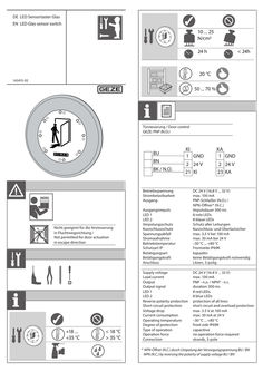
LED sensor switch glass
DE LED Sensortaster Glas EN LED Glas sensor switch 10 ... 25 N/cm2 24 h < 24h 20 °C 143415-02 50 ... 70 % T Türsteuerung / Door control GEZE: PNP (N.O.) BU BN BK / N.O. KI … GND KA … GND … 24 V 21 KI … 24 V 23 KA Ausgangsimpuls LED … LED … Verpolungsschutz Kurzschlussschutz Spannungsabfall Stromaufnahme Betriebstemperatur Schutzart IP Betätigungsart Betätigungskraft Anschluss DC 24 V (16,8 V ... 32 V) max. 100 mA PNP-Schließer (N.O.) / NPN-Öffner* (N.C.) Impulsdauer 300 ms … rote LEDs … blaue LEDs Schutz aller Leitungen Kurzschluss- und Überlastsicher max. 3,5 V bei 100 mA max. 30 mA bei 24 V –30 °C ... +80 °C Frontseite IP69K kapazitiv keine Betätigungskraft notwendig Litzen, 3-polig Supply voltage Load current Output Output signal LED … LED … Reverse polarity protection Short-circuit protection Voltage drop Current consumption Operating temperature Degree of protection Type of operation Operation force Connection DC 24 V ( … V ... 32 V) max. 100 mA PNP - n.o. / NPN* - n.c. duration 300 ms … red LEDs … blue LEDs protection of all lines short circuit and overload protection max. … V at 100 mA max. 30 mA at 24 V –30 °C ... +80 °C front side IP69K capacitive no operation force required strands, 3-pole Betriebsspannung Strombelastbarkeit Ausgang Nicht geeignet für die Ansteuerung in Fluchtwegsrichtung / Not permitted for door actuation in escape direction +18 ... +35 °C < 18 °C > 35 °C * NPN-Öffner (N.C.) durch Umpolung der Versorgungsspannung BU / BN NPN (N.C.) by reversing the polarity of supply voltage BU / BN … 5 Ø 79 Ø 60 Ø 100 143412 … 200 … 20 … Ø 115 184805 Ø 10 Ø6 Ø 88 … 1 max. Ø 79–80 mm … 2 … 1 … GEZE GmbH Reinhold-Vöster-Straße 21–29 71229 Leonberg Germany Tel.: 0049 7152 203 … Fax: 0049 7152 203 310 www.geze.com 4
PDF | 2 MB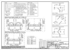
TSA 160 NT
PDF | 244 KB
Standard cable plan ECturn Inside
DWG | 193 KB

Slimdrive EMD, EMD-F mechanical replacement unit
Slimdrive EMD Slimdrive EMD-F DE Umbauanleitung GB Replacement instructions Mechanische Austauscheinheit Mechanical replacement unit … Slimdrive EMD/EMD-F Inhaltsverzeichnis / Contents … 1 Symbole und Darstellungsmittel / Symbols and means of representation … 2 Produkthaftung / Product liability … 3 Mitgeltende Dokumente / Additional applicable documents … 4 Sicherheit / Safety … Bestimmungsgemäße Verwendung / Intended use … Sicherheitshinweise / Safety instructions … Umweltbewusstes Arbeiten / Environmentally-conscious working … 5 Werkzeuge und Hilfsmittel / Tools and aids … 6 Umbau / Replacement … Elektrische Zuleitungen abklemmen / Disconnecting electrical supply cables … Antrieb demontieren / Dismantling the drive … Transformator und Steuerung demontieren / Dismantling the transformer and control unit … 11 Transformator und Steuerung in neue mechanische Austauscheinheit einbauen / Install the transformer and control unit into the new mechanical replacement unit … 12 … Antrieb montieren / Mounting the drive … 14 Slimdrive EMD/EMD-F … Symbole und Darstellungsmittel / Symbols and means of representation Symbole und Darstellungsmittel / Symbols and means of representation Warnhinweise / Warnings In dieser Anleitung werden Warnhinweise verwendet, um Sie vor Sach- und Personenschäden zu warnen. XX Lesen und beachten Sie diese Warnhinweise immer. XX Befolgen Sie alle Maßnahmen, die mit dem Warnsymbol und Warnwort gekennzeichnet sind. In these instructions, warnings are used to warn against material damage and injuries. XX Always read and observe these warnings. XX Observe all the measures that are marked with the warning symbol and warning word. Warnsymbol Warning symbol Warnwort Bedeutung Warning word Meaning Gefahren für Personen. WARNUNG Nichtbeachtung kann zu Tod oder schweren Verletzungen führen. WARNING VORSICHT CAUTION Danger for persons. Non-compliance can result in death or serious injuries. Gefahren für Personen. Nichtbeachtung kann zu leichten Verletzungen führen. Danger for persons. Non-compliance can result in minor injuries. Weitere Symbole und Darstellungsmittel / Further symbols and means of representation Um die korrekte Bedienung zu verdeutlichen, sind wichtige Informationen und technische Hinweise besonders herausgestellt. Important information and technical notes are emphasised in order to illustrate the correct operation. Symbol Bedeutung Meaning bedeutet „Wichtiger Hinweis“ means “important note” bedeutet „Zusätzliche Information“ means “additional information” XX Symbol für eine Handlung: Hier müssen Sie etwas tun. XX Halten Sie bei mehreren Handlungsschritten die Reihenfolge ein. Symbol for an action: Here you have to do something. XX Observe the sequence if there are several action steps. … Produkthaftung / Product liability Gemäß der im Produkthaftungsgesetz definierten Haftung des Herstellers für seine Produkte sind die in dieser Broschüre enthaltenen Informationen (Produktinformationen und bestimmungsgemäße Verwendung, Fehlgebrauch, Produktleistung, Produktwartung, Informations- und Instruktionspflichten) zu beachten. Die Nichtbeachtung entbindet den Hersteller von seiner Haftungspflicht. In accordance with the liability of manufacturers for their products as defined in the German “Produkthaftungsgesetz” (Product Liability Act), the information contained in these instructions (product information and proper use, misuse, product performance, product maintenance, obligations to provide information and instructions) is to be observed. Non-compliance releases the manufacturer from its statutory liability. … Mitgeltende Dokumente / Additional applicable documents … Mitgeltende Dokumente / Additional applicable documents Art Type Anschlussplan EMD EMD wiring diagram Kabelplan EMD EMD cable plan Montageanleitung Slimdrive EMD/EMD-F Slimdrive EMD/EMD-F mounting instructions … Slimdrive EMD/EMD-F Materialnummer/Zeichnungsnummer Material number/Drawing number 138949 70106-9-0971 117956 Sicherheit / Safety Für die Sicherheit von Personen ist es wichtig, diesen Sicherheitsanweisungen Folge zu leisten. Diese Anweisungen sind aufzubewahren. To ensure personal safety, it is important to follow these safety instructions. These instructions are to be retained. … Bestimmungsgemäße Verwendung / Intended use Der Slimdrive EMD/EMD-F ist ausschließlich geeignet für den Einsatz àà in trockenen Räumen, àà im Eingangs- und Innenbereich des Fußgängerverkehrs in gewerblichen Betriebsstätten und öffentlichen Bereichen, àà im Privatbereich. Der Slimdrive EMD àà darf nicht an Flucht- und Rettungswegen eingesetzt werden, àà darf nicht an Feuer- oder Rauchschutztüren eingesetzt werden, àà darf nicht für den EX-Bereich eingesetzt werden. Der Slimdrive EMD-F àà darf an Flucht- und Rettungswegtüren eingesetzt werden, àà ist für den Einsatz an Feuer- oder Rauchschutztüren vorgesehen, àà darf nicht für den EX-Bereich eingesetzt werden. Die Sensor-Gleitschiene darf ausschließlich zur Montage der Sensorleiste verwendet werden. Anderer Einsatz als der bestimmungsgemäße Gebrauch, wie z .B. dauerhafter manueller Betrieb, sowie alle Veränderungen am Produkt sind unzulässig. Beachten Sie die „GEZE Produktinformationen für Türschließer“. The Slimdrive EMD/EMD-F is designed solely for use àà in dry rooms, àà in entrances and interior areas of pedestrian traffic in commercial plants and public areas, àà in private areas. The Slimdrive EMD àà may not be used at escape and rescue routes, àà may not be used at fire or smoke proof doors, àà may not be used for hazardous areas. The Slimdrive EMD-F àà may be used at escape and rescue route doors, àà is designed for use at fire or smoke proof doors, àà may not be used for hazardous areas. The sensor guide rail may only be used to mount the sensor strip. Any other use than the proper use, such as permanent manual operation, as well as all changes to the product are impermissible. Observe the “GEZE Product information for door closers”. … Slimdrive EMD/EMD-F … Sicherheit / Safety Sicherheitshinweise / Safety instructions àà Von GEZE vorgeschriebene Betriebs-, Wartungs- und Instandhaltungsbedingungen einhalten. àà Inbetriebnahme, vorgeschriebene Montage, Wartungs- und Instandsetzungsarbeiten müssen von Sachkundigen durchgeführt werden, die von GEZE autorisiert sind. àà Bei eigenmächtigen Veränderungen an der Anlage übernimmt GEZE keine Haftung für daraus resultierende Schäden. àà Der Betreiber ist verantwortlich für den sicheren Betrieb der Anlage. Sollten Sicherheitseinrichtungen verstellt sein und somit nicht mehr ihren vorbestimmten Zweck erfüllen, ist ein Weiterbetrieb nicht mehr gestattet. Der Servicetechniker ist umgehend zu informieren. àà Bei Kombination mit Fremdfabrikaten übernimmt GEZE keine Gewährleistung. Auch für Reparatur- und Wartungsarbeiten dürfen nur GEZE-Originalteile verwendet werden. àà Der Anschluss an die Netzspannung muss von einer Elektrofachkraft ausgeführt werden. Netzanschluss und Schutzleiterprüfung entsprechend DIN VDE 0100-610 durchführen. àà Als netzseitige Trennvorrichtung einen bauseitigen 10-A-Sicherungsautomaten verwenden, der die Anlage vom Netz trennt. àà Gemäß der Maschinenrichtlinie 2006/42/EG und der DIN 18650 muss vor Inbetriebnahme der Türanlage eine Sicherheitsanalyse (Gefahrenanalyse) durchgeführt werden und die Türanlage gemäß CE-Kennzeichnungsrichtlinie 98/68/EWG gekennzeichnet werden. àà Den neuesten Stand von Richtlinien, Normen und länderspezifischen Vorschriften beachten, insbesondere: - BGR 232 „Richtlinien für kraftbetätigte Fenster, Türen und Tore“ - DIN 18650 „Schlösser und Beschläge - Automatische Türsysteme“ - DIN VDE 0100-610 „Errichten von Niederspannungsanlagen“ - DIN EN 60335-2-103 „Sicherheit elektrischer Geräte für den Hausgebrauch und ähnliche Zwecke; Besondere Anforderungen für Antriebe, für Tore, Türen und Fenster“ - Unfallverhütungsvorschriften, insbesondere BGV A1 „Allgemeine Vorschriften“ und BGV A3 „Elektrische Anlagen und Betriebsmittel“ àà Operating, maintenance and repair conditions specified by GEZE must be observed. àà The commissioning, prescribed installation, maintenance and repair work must be performed by properly trained personnel authorised by GEZE. àà GEZE shall assume no liability for damage caused by unauthorised changes to the system. àà The owner is responsible for safe operation of the system. If safety equipment is misaligned, causing it to no longer fulfil its intended purpose, further operation is not permissible. Inform the service technician immediately in this case. àà GEZE shall not be liable if products from other manufacturers are used with GEZE equipment. Only original GEZE parts may be used for repair and maintenance work as well. àà The connection to the power supply must be made by a professional electrician. Perform the power connection and safety earth conductor test in accordance with DIN VDE 0100-610. àà Use a customer-accessible 10-A overload cut-out that disconnects the system from the power supply as the line-side disconnecting device. àà In accordance with Machinery Directive 2006/42/EC and DIN 18650, a risk analysis must be performed and the door system identified in accordance with CE Identification Directive 98/68/EEC before commissioning the door system. àà Observe the latest versions of guidelines, standards and country-specific regulations, in particular: - BGR 232 “Guidelines for power-operated windows, doors and gates“ - DIN 18650 “Building hardware - Powered pedestrian doors“ - DIN VDE 0100-610 “Installation of low-voltage systems“ - DIN EN 60335-2-103 “Safety of electrical devices for home use and similar purposes; special requirements for drives for gates, doors and windows“ - Accident-prevention regulations, especially BGV A1 “General regulations“ and BGV A3 “Electrical systems and equipment“ … Werkzeuge und Hilfsmittel / Tools and aids … Slimdrive EMD/EMD-F Umweltbewusstes Arbeiten / Environmentally-conscious working àà Bei der Entsorgung der Türanlage die verschiedenen Materialien trennen und der Wiederverwertung zuführen. àà Batterien und Akkumulatoren nicht mit dem Hausmüll entsorgen. àà Bei der Entsorgung der Türanlage und Batterien/Akkumulatoren die gesetzlichen Bestimmungen einhalten. àà When disposing of the door system, separate the different materials and have them recycled. àà Do not dispose of batteries and storage cells with household garbage. àà Comply with the statutory regulations when disposing of the door system and the batteries and storage cells. … 6 Werkzeuge und Hilfsmittel / Tools and aids àà àà àà àà àà Schraubendrehersatz Kreuzschlitz-Schraubendrehersatz Hakenschlüssel DRM 20-22 (ID111247) Innensechskant-Schlüsselsatz Drehmomentschlüssel àà àà àà àà àà Screwdriver set Crosstip screwdriver set Hook wrench DRM 20-22 (ID111247) Socket hexagon-head screw key set Torque spanner Slimdrive EMD/EMD-F Umbau / Replacement … Umbau / Replacement … Elektrische Zuleitungen abklemmen / Disconnecting electrical supply cables Warnung! Lebensgefahr durch Stromschlag. XX Elektrische Anlage (230 V) nur von einer Elektrofachkraft trennen lassen. Warning! Danger of fatal injury through electric shock. XX The electrical system (230 V) may only be disconnected by a professional electrician. � � XX XX XX XX XX XX Gebäudeseitig den Antrieb vom Stromnetz trennen. Haube (2) vorsichtig abnehmen. Haubenerdung (1) abziehen und Haube ganz abnehmen. Disconnect the drive from the power supply at the building end. Remove the hood (2) carefully. Pull off the hood earthing (1) and remove the hood completely. … Umbau / Replacement Slimdrive EMD/EMD-F � XX Kabel vom Klemmenblock (3) lösen. XX Loosen the cable at the terminal block (3). … Antrieb demontieren / Dismantling the drive … .1 Antrieb mit Gestänge / Drive with link arm � � � � XX Tür (4) schließen. Vorsicht! Quetschgefahr durch unkontrollierte Bewegung des Hebels. XX Beim Lösen der Schraube (2) nicht in den Bewegungsbereich des Hebels greifen. XX Close the door (4). Caution! Danger of crushing through uncontrolled movement of the lever. XX When loosening the screw (2) do not reach into the range of movement of the lever. … Slimdrive EMD/EMD-F XX XX XX XX XX XX … .2 Umbau / Replacement Schrauben (2) lösen. Die restliche Federvorspannung bewegt den Hebel (1) um einige Winkelgrad bis zum mechanischen Anschlag. Innensechskantschraube (3) herausschrauben. Gestänge abnehmen. Loosen the screws (2). The residual spring pretension moves the lever (1) by a few degrees up to the mechanical stop. Screw out the hexagon socket-head screw (3). Remove the link arm. Antrieb mit Rollenschiene / Drive with roller guide rail � � � XX Tür (1) mindestens 10° öffnen und festsetzen. Vorsicht! Quetschgefahr durch unkontrollierte Bewegung des Rollenhebels. XX Beim Aushängen des Rollenhebels (3) nicht in den Bewegungsbereich des Rollenhebels greifen. XX XX XX Rollenhebel (3) aus Schiene aushängen. Rollenhebel dreht sich langsam bis zum mechanischen Anschlag. Innensechskantschraube (2) lösen. Der Rollenhebel (3) ist jetzt vom Antrieb getrennt. Open the door (1) at least 10° and fix it there. Caution! Danger of crushing through uncontrolled movement of the roller lever. XX When hanging out the roller lever (3) do not reach into the range of movement of the roller lever. XX XX Hang the roller lever (3) out of the rail. Roller lever turns slowly up to the mechanical stop. Loosen the hexagon socket-head screw (2). The roller lever (3) is now disconnected from the drive. … Umbau / Replacement … .3 Slimdrive EMD/EMD-F Antrieb abschrauben / Unscrewing the drive � � XX … Schrauben (2) abschrauben und Antrieb (1) abnehmen. WARNUNG! Verletzungsgefahr durch unter mechanischer Spannung stehende Teile! XX Energiespeicher und Motor-Getriebeeinheit des Slimdrive EMD-F nicht demontieren. XX Unscrew the … screws (2) and remove the drive (1). WARNING! Danger of injury through parts subject to mechanical tension! XX Do not dismantle the energy storage and motor gearing-unit of the Slimdrive EMD-F. 10 Slimdrive EMD/EMD-F Umbau / Replacement … Transformator und Steuerung demontieren / Dismantling the transformer and control unit … .1 Steuerung demontieren / Dismantling the control unit � � XX XX XX XX … .2 Alle elektrischen Verbindungen zur Steuerung (1) abziehen und lösen. … Schrauben (2) abschrauben und Steuerung (1) abnehmen. Pull off and loosen all the electrical connections to the control unit (1). Unscrew the … screws (2) and remove the control unit (1). Transformator demontieren / Dismantling the transformer � � XX XX XX XX XX XX Elektrische Steckverbindungen abnehmen. Schraube (1) aus dem Transformator schrauben. Transformator (2) abnehmen. Remove the electrical connectors. Screw the screw (1) out of the transformer. Remove the transformer (2). 11 Umbau / Replacement Slimdrive EMD/EMD-F � � XX … Schrauben (4) abschrauben und Halteblech (3) abnehmen. XX Unscrew the … screws (4) and remove the retaining plate (3). … Transformator und Steuerung in neue mechanische Austauscheinheit einbauen / Install the transformer and control unit into the new mechanical replacement unit … .1 Steuerung montieren / Mounting the control unit � � XX XX XX XX 12 Steuerung (1) mit … Schrauben (2) in die neue mechanische Austauscheinheit schrauben. Elektrische Verbindungen an die Steuerung anschließen. Screw the control unit (1) into the new mechanical replacement unit with … screws (2). Connect the electrical connections to the control unit. Slimdrive EMD/EMD-F … .2 Umbau / Replacement Transformator montieren / Mounting the transformer � � XX Halteblech (1) mit … Schrauben (2) festschrauben. XX Screw on the retaining plate (1) with … screws (2). � � XX XX XX XX Transformator (4) mit Schraube (3) an das Halteblech schrauben. Elektrische Steckverbindungen an den Transformator anschließen. Screw the transformer (4) to the retaining plate with the screw (3). Connect the electrical connectors to the transformer. 13 Antrieb montieren / Mounting the drive … Slimdrive EMD/EMD-F Antrieb montieren / Mounting the drive Die Arbeitsanweisungen zur Montage des Antriebs sind in der Montage- und Serviceanleitung „Slimdrive EMD/ EMD-F“ beschrieben. The work instructions for mounting the drive are contained in the “Slimdrive EMD/EMD-F” mounting and service instructions. 14 Slimdrive EMD/EMD-F Antrieb montieren / Mounting the drive 15 Germany GEZE Sonderkonstruktionen GmbH Planken … 97944 Boxberg-Schweigern Tel. +49 (0) 7930-9294-0 Fax +49 (0) 7930-9294-10 E-Mail: sk.de@geze.com Germany GEZE GmbH Niederlassung Nord/Ost Bühringstraße … 13086 Berlin (Weissensee) Tel. +49 (0) 30-47 89 90-0 Fax +49 (0) 30-47 89 90-17 E-Mail: berlin.de@geze.com Germany GEZE GmbH Niederlassung West Nordsternstraße 65 45329 Essen Tel. +49 (0) 201-83082-0 Fax +49 (0) 201-83082-20 E-Mail: essen.de@geze.com Germany GEZE GmbH Niederlassung Mitte Adenauerallee … 61440 Oberursel (b. Frankfurt) Tel. +49 (0) 6171-63610-0 Fax +49 (0) 6171-63610-1 E-Mail: frankfurt.de@geze.com Germany GEZE GmbH Niederlassung Süd Breitwiesenstraße … 71229 Leonberg Tel. +49 (0) 7152-203-594 Fax +49 (0) 7152-203-438 E-Mail: leonberg.de@geze.com Germany GEZE Service GmbH Reinhold-Vöster-Straße 25 71229 Leonberg Tel. +49 (0) 7152-9233-0 Fax +49 (0) 7152-9233-60 E-Mail: service-info.de@geze.com Germany GEZE Service GmbH Niederlassung Berlin Bühringstraße … 13086 Berlin (Weissensee) Tel. +49 (0) 30-470217-30 Fax +49 (0) 30-470217-33 E-Mail: service-info.de@geze.com Austria GEZE Austria GmbH Wiener Bundesstrasse 85 5300 Hallwang b. Salzburg Tel. +43-(0)662-663142 Fax +43-(0)662-663142-15 E-Mail: austria.at@geze.com Baltic States GEZE GmbH Baltic States office Dzelzavas iela 120 S 1021 Riga Tel. +371 (0) 67 89 60 35 Fax +371 (0) 67 89 60 36 E-Mail: office-latvia@geze.com GEZE GmbH P.O.Box 1363 Reinhold-Vöster-Straße 21–29 71229 Leonberg Germany Benelux GEZE Benelux B.V. Leemkuil … Industrieterrein Kapelbeemd 5626 EA Eindhoven Tel. +31-(0)40-26290-80 Fax +31-(0)40-26 290-85 E-Mail: benelux.nl@geze.com Bulgaria GEZE Bulgaria - Trade Representative Office 61 Pirinski Prohod, entrance „B“, 4th floor, office 5, 1680 Sofia Tel. +359 (0) 24 70 43 73 Fax +359 (0) 24 70 62 62 E-Mail: office-bulgaria@geze.com China GEZE Industries (Tianjin) Co., Ltd. Shuangchenzhong Road Beichen Economic Development Area (BEDA) Tianjin 300400, P.R. China Tel. +86(0)22-26973995-0 Fax +86(0)22-26972702 E-Mail: Sales-info@geze.com.cn China GEZE Industries (Tianjin) Co., Ltd. Branch Office Shanghai Unit 25N, Cross Region Plaza No. 899, Ling Ling Road, XuHui District 200030 Shanghai, P.R. China Tel. +86 (0)21-523 40 960 Fax +86 (0)21-644 72 007 E-Mail: chinasales@geze.com.cn China GEZE Industries (Tianjin) Co., Ltd. Branch Office Guangzhou Room 17C3 Everbright Bank Building, No.689 Tian He Bei Road 510630 Guangzhou, P.R. China Tel. +86(0)20-38731842 Fax +86(0)20-38731834 E-Mail: chinasales@geze.com.cn China GEZE Industries (Tianjin) Co., Ltd. Branch Office Beijing Room 1001, Tower D Sanlitun SOHO No. 8, Gongti North Road, Chaoyang District, 100027 Beijing, P.R.China Tel. +86-(0)10-5935 9300 Fax +86-(0)10-5935 9322 E-Mail: chinasales@geze.com.cn China GEZE Industries (Tianjin) Co., Ltd. Branch Office Singapore 21, Bukit Batok Crescent, No. 23-75, Wcega Tower, Singapore 658065 Tel. +65-6846 1338 Fax +65-6846 9353 E-Mail: gezesea@geze.com.sg Hungary GEZE Hungary Kft. Bartók Béla út 105-113. Budapest H-1115 Tel. +36 (1) 481 4670 Fax +36 (1) 481 4671 E-Mail: office-hungary@geze.com Iberia GEZE Iberia S.R.L. Pol. Ind. El Pla C/Comerc, 2-22, Nave 12 08980 Sant Feliu de Llobregat (Barcelona) Tel. +34 9-02 19 40 36 Fax +34 9-02 19 40 35 E-Mail: info@geze.es India GEZE India Private Ltd. MF2 & 3, Guindy Industrial Estate Ekkattuthangal Chennai - 600 097 Tamilnadu Tel. +91 (0) 44 30 61 69 00 Fax +91 (0) 44 30 61 69 01 E-Mail: office-india@geze.com Italy GEZE Italia Srl Via Giotto, … 20040 Cambiago (MI) Tel. +3902950695-11 Fax +3902950695-33 E-Mail: italia.it@geze.com Italy GEZE Engineering Roma Srl Via Lucrezia Romana, 91 00178 Roma Tel. +3906-7265311 Fax +3906-72653136 E-Mail: roma@geze.biz Kazakhstan GEZE Central Asia 050061, Almaty, Kasakhstan Rayimbek ave. 348, A, office 310 Tel. +7 (0) 72 72 44 78 03 Fax +7 (0) 72 72 44 78 03 E-Mail: office-kazakhstan@geze.com Poland GEZE Polska Sp.z o.o. ul. Annopol 21 03-236 Warszawa Tel. +48 (0)22 440 … 440 Fax +48 (0)22 440 … 400 E-Mail: geze.pl@geze.com Romania GEZE Romania S.R.L. IRIDE Business Park Building nr. 10, level … Str. Dimitrie Pompei nr. 9–9a RO-020335 Bucharest, sector … Tel. +40 (0) 316 201 257 Fax +40 (0) 316 201 258 E-Mail: office-romania@geze.com Russian Federation GEZE GmbH Representative Office Russia Kolodesnij pereulok3, str. 25 Office Nr. 5201-5203 107076 Moskau Tel. +7 (0) 49 55 89 90 52 Fax +7 (0) 49 55 89 90 51 E-Mail: office-russia@geze.com France GEZE France S.A.R.L. ZAC de l’Orme Rond RN 19 77170 Servon Tel. +33-(0)1-606260-70 Fax +33-(0)1-606260-71 E-Mail: france.fr@geze.com Scandinavia GEZE Scandinavia AB Mallslingan 10 Box 7060 18711 Täby, Sweden Tel. +46(0)8-7323-400 Fax +46(0)8-7323-499 E-Mail: sverige.se@geze.com Tel.: 0049 7152 203-0 Fax: 0049 7152 203-310 www.geze.com 144030-00 Scandinavia GEZE Norway Industriveien 34 B 2072 Dal Tel. +47(0)639-57200 Fax +47(0)639-57173 E-Mail: norge.se@geze.com Scandinavia GEZE Finland Postbox 20 15871 Hollola Tel. +358(0)10-4005100 Fax +358(0)10-4005120 E-Mail: finland.se@geze.com Scandinavia GEZE Denmark Mårkærvej 13 J-K 2630 Taastrup Tel. +45(0)46-323324 Fax +45(0)46-323326 E-Mail: danmark.se@geze.com South Africa DCLSA Distributors (Pty.) Ltd. 118 Richards Drive, Midrand, Halfway House Ext. 111 P.O. Box 7934 Midrand 1685 Tel. +27(0)113158286 Fax +27(0)113158261 E-Mail: info@dclsa.co.za Switzerland GEZE Schweiz AG Bodenackerstrasse 79 4657 Dulliken Tel. +41-(0)62-2855400 Fax +41-(0)62-2855401 E-Mail: schweiz.ch@geze.com Turkey GEZE GmbH Türkiye - İstanbul İrtibat Bürosu Ataşehir Bulvarı, Ata 2/3 Plaza Kat: … D: 84 Ataşehir Kadıköy / İstanbul Tel. + 90 (0) 21 64 55 43 15 Fax + 90 (0) 21 64 55 82 15 E-Mail: office-turkey@geze.com Ukraine Repräsentanz GEZE Ukraine TOV ul. Viskoznaya, 17, building 93-B, office 12 02094 Kiev Tel. +38 (0) 44 501 22 25 Fax +38 (0) 44 499 77 25 E-Mail: office-ukraine@geze.com United Arab Emirates/GCC GEZE Middle East P.O. Box 17903 Jebel Ali Free Zone Dubai Tel. +971(0)4-8833112 Fax +971(0)4-8833240 E-Mail: geze@emirates.net.ae United Kingdom GEZE UK Ltd. Blenheim Way Fradley Park Lichfield Staffordshire WS13 8SY Tel. +44(0)1543443000 Fax +44(0)1543443001 E-Mail: info.uk@geze.com
PDF | 2 MB